Some objects look easy to create, but are actually difficult, while other objects look harder to build, but are actually fairly simple. This is all down to what workflows can be used to create an object or type of object. A wire mesh is an example of an object that looks hard but is actually easy.
To transform any mesh object into a wireframe first select the object and then go to Properties > Modifiers and bring up the list for adding modifiers. In the generate list, select the wireframe option. Alternatively, select all of the geometry in edit mode, then go to the face menu and select wireframe from the list.
Each method behaves slightly differently, especially when you start using other modifiers such as the subdivision surface modifier. However, the result is usually the same, it’s just a matter of choosing your workflow.
Should I Use The Wireframe Tool Or The Wireframe Modifier?
Both of these will give you the required result, a wireframe mesh based on the geometry of your model, but there are a couple of differences between the two.
First, a standard tool like the wireframe tool found in the face menu is a destructive tool that, once the settings of the tool have been confirmed, will make permanent changes to the 3D model.
On the other hand, a modifier is used as a part of a non-destructive workflow where the effect of the modifier can be turned on and off, and it can be combined with other modifiers in various ways.
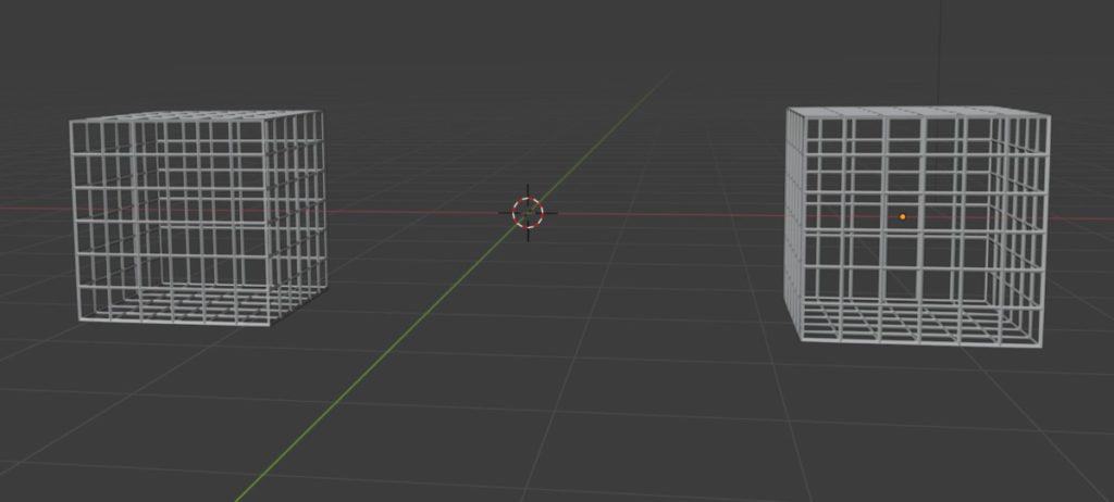
Looking at the image above, we have two cages, one has been created using the wireframe tool on a subdivided cube (Left) and the other created using the wireframe modifier on an identical object (Right). The thickness value has been set to 0.04 for both objects, and as you can see, they are identical.
The object that has been created using the modifier is more flexible and works better with other modifiers because it can be repositioned in the modifier stack.
For example, below you see the subdivision surface modifier assigned to both objects, and they both look the same. For the object on the left, it is the only modifier in the stack, while for the object on the right it is below the wireframe modifier since it was added after.
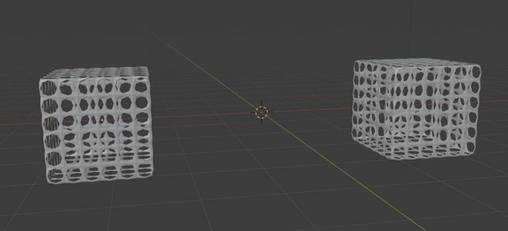
For the object on the left, we can edit the number of subdivisions to improve the look if we want, but not much else beyond it. With the modifier-based wireframe, we can change the order of the modifiers in the modifier stack, which changes the outputted result.
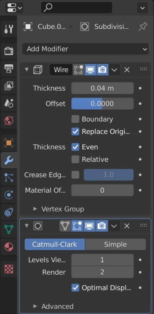
Above is how it should look after we add the Subsurf modifier, and we can grab and move a modifier by clicking on the icon in the corner of any modifier and then reposition the Subsurf to the top.
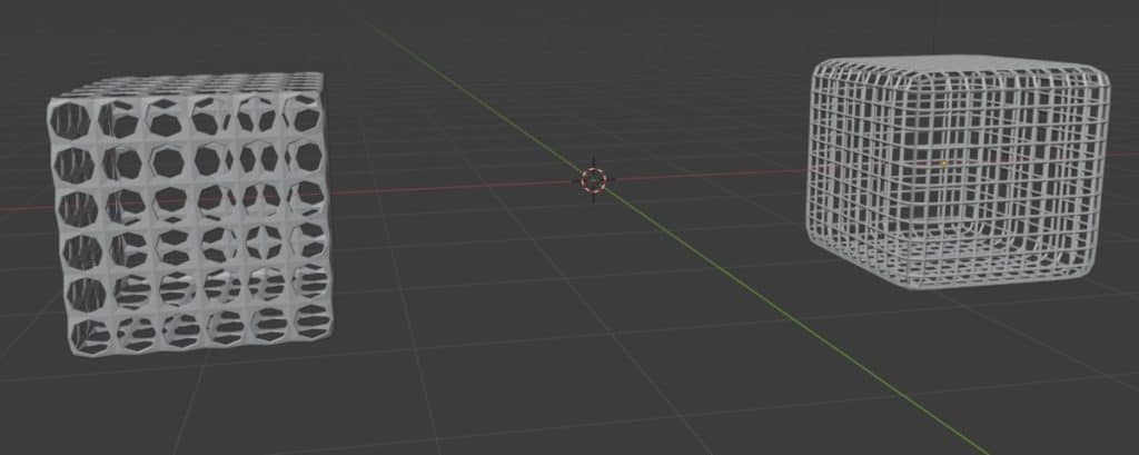
As you can see, changing the order of the modifiers has a substantial impact on the look of the model.
The wireframe modifier, and tool for that matter, delete all of the faces on a model before creating new geometry based on the positioning of the vertices and edges. So if you want to keep the general shape of the object, then the wireframe needs to be created as late as possible.
Overall though, you should be looking to use the modifier more often because it is easier to access while also providing the added versatility that comes with a non-destructive workflow.
Why Is It Important To Follow A Non-Destructive Workflow?
We have used this term a couple of times to describe the use of the wireframe modifier. But why is it so important to have this kind of workflow?
Well for one the changes that you make when using a tool like a modifier only become permanent when that modifier is applied. As long as the modifier exists in the modifier stack then you will be able to edit its settings, reposition it in the modifier stack and even disable its effect in the viewport.
By comparison, a standard tool follows a much more linear workflow, once the tool has been used the only way to correct an error or change a parameter is to use the undo feature to go back to before the tool is used. This could also mean reverting other changes made after the wireframe tool was used.
This is what we mean when we describe it as a destructive workflow, where deciding to go back and correct an error or change a setting on a tool can cost you several minutes of work time, maybe more.
What Else Can I Do With The Wireframe Modifier?
Most modifiers are relatively straightforward in what they are designed to do and are very effective when they are combined with the functionality of other modifiers, such as combined Wireframe and Subsurf modifiers to create the rounded cage.
With the modifier itself, there are a few parameters that you can change. The most obvious of which is the thickness value of the wired mesh, which we recommend setting to a low value for this type of object.
The Offset Value
The offset value determines where the mesh is created based on the positioning of the original edges. A value of 0 will generate the mesh using the original edges as the center point. At -1 the geometry is created on the inside of the edges while a value of 1 generates geometry on the outside.
You will see the change as you adjust the offset but the behavior is more noticeable when you then adjust the thickness.
For example, by setting the offset to -1 and increasing the thickness you will see that the mesh does get thicker, but it moves towards the center of the object, keeping the scale of the object the same.
By comparison, setting the offset to 1 will make the geometry on the outside thicker, but keeping the space on the inside as it was.
Keep Original Object
If you want to create the mesh, but don’t want to get rid of the original geometry, then you can turn off the replace geometry option, which keeps the original object in place.
Thickness Calculators
You may be confused to see more options that are labeled under thickness, however, the options here change the way the thickness value above is calculated.
For example, the even option scales the thickness evenly across the entire model using the offset, while the relative option scales the thickness based on the surrounding geometry.
Generally keep the even option ticked, while the relative option will usually make the wired mesh considerably smaller because of how it is calculated.
Using The Material Index
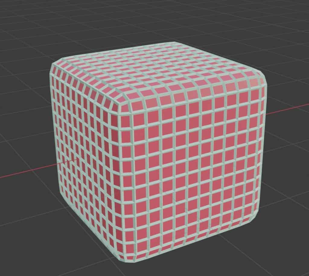
This option works well when you are also maintaining the original. Let’s say the object has a material that has been assigned to it. When we transform the object to a wired mesh it maintains the material that was assigned, but what if want this to be a different material.
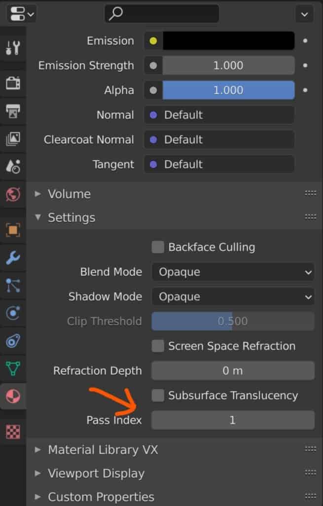
If you go to Properties > Materials > Settings you will find an option for the material pass index that is set to 0. You can create a second material and set the pass index to 1, then go back to the modifier and increase the material offset value to 1. This will change the color of the mesh to the material that matches the index value.
Influencing With Vertex Groups
Sometimes you may want to only set up a wired mesh on a specific area of the model. You can influence this by creating a vertex group. Go to Properties > Object Data > Vertex Group, select the geometry you want to add in edit mode, and press the plus button to name the new group.
Then come back to the modifier and connect that vertex group to the modifier. At this point, the wireframe will only be generated for the vertex group.
You can click on the double arrow icon to invert the effect so that the vertex group is excluded from the wired mesh.
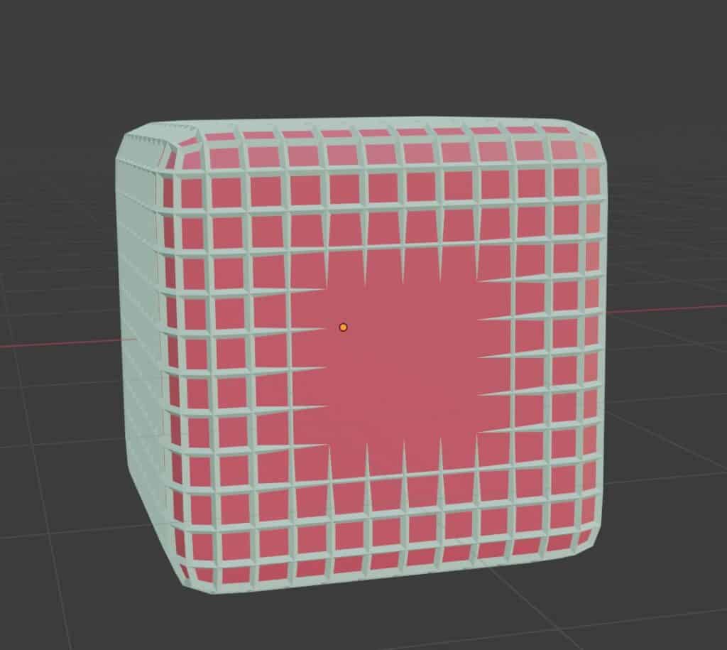
You can also change the factor which determines how strong the effect is on the model. A value of 0 will use just the vertex group, while a value of 1 is the same as not using it at all.
Here Are Some Other Articles We Think You May Be Interested In
Thanks for taking the time to read this article, we hope you found it helpful. We have gathered a small list of other articles on this website that we believe may be of interest to you.
- Isolate A Single Object For Editing In The Viewport
- Remove All The 3D Gridlines In The Viewport
- Why Can I Not Zoom Into My Viewport Anymore?
- Can I Learn Blender On My Own?
- What Are Normals In 3D Modeling?
-
Custom Normals: Blender Hard Surface Tip
Enhancing hard surface models with custom normals for realism.
-
Align Perfectly with Blender’s Snap Tools
Aligning objects perfectly with Blender’s advanced Snap tools.
-
Mechanical Parts: Blender Modelling Guide
Detailed guide to modeling mechanical parts with precision in Blender.