There are many functions for a 3D modeling application, from designing assets for video games to the development of designs for 3D printing. Blender is capable of a lot of different tasks and functions, but how effective is it for creating blueprint-style drawings?
Blender can be used to create Blueprints of designs, especially when those designs are three-dimensional. It does not do so well with technical drawings, often used to create blueprints, but it can be made more effective thanks to the CAD Sketcher add-on.
If you are using Blender for more technical tasks and workflows, then it can be a good idea to create technical drawings and Blueprints of your designs so that you can either replicate the design in the future or sell it to other artists to use.
What Is A Blueprint?
A blueprint is a technical drawing of a complicated design, normally of a mechanical object such as a vehicle, and offers views of the design from various angles and includes specifications for the design’s structure.
You will find blueprints are most common in the industries of vehicle design as well as architecture. Any industry that requires complicated building schematics will require blueprints of the design.
The images provided in blueprints are typically two-dimensional. However, you can have free dimensional shapes projected as images for blueprints, provided that you follow certain rules.
Can You Create Blueprints Within Blender?
It is possible to create your own blueprints within Blender, although other applications are better suited.
Certain applications are referred to as CAD software, which is short for computer-aided design. Some of these applications allow you to create 2D technical drawings, which are effectively blueprints, depending on how those drawings are formatted.
One of the most notable examples is AutoCAD software, which prioritizes the ability to create highly detailed schematics and technical drawings of complicated designs. This application is built from the ground up to allow you to create images and blueprints of any potential objects or products that you wish to create.
My comparison blender is not as suitable for creating blueprints and technical drawings because it needs to be structured in a specific way to create these drawings. However, this does not mean you can’t create blueprints using Blender. You just have to know which tools to use.
Importing Blueprints With Reference Images
While this is not strictly a way of creating blueprints within Blender, it brings in existing blueprints to use as reference material. Blender allows you to import images of almost any kind, and it allows you to do this either within the image editor or in the 3D viewport itself as a reference image.
This will be very useful if you are looking to create the objects within Blender and you require the reference material to do so. When we are looking to create the blueprint itself within Blender, we are reversing this process, creating the blueprint so that others can create our models.
If you want to add an image within the image editor, simply go to the open button, which will open up the file browser. Then locate the image you wish to import and select the blue button.
Your target image will now appear in the image editor, and you can use it as reference material while working on your project.
You can also use your reference material within the 3D viewports. To add an image, press the Shift + A hotkey to open up the add menu. From this menu, go where it says image, and then you will have several options.
You can choose to import an image as reference material, or you can choose to import it as a background image. There is a very small difference between these two options.
If you plan to have your image act as a reference, you can add it to your scene and grab the image as it becomes an actual object. You can position it to the side as additional reference material while working on your model.
On the other hand, you can use it as a background image where you can manipulate settings such as the opacity so that you can view your reference material while modeling the object itself and use it almost as a guide for the structure of the object.
In practice, though, the options and functionality of the image barely change, regardless of whether you import it as a reference image or as a background image.
Creating Reference Material With Orthographic Views
If you are not looking to bring in reference images to create objects within Blender, then you likely want to create your blueprints using your existing objects. There are certain rules that we need to follow if we are to create good blueprints within the 3D viewport. Remember that our blueprints are effectively 2D images.
Therefore, we first need to know how to create these specific perspectives of our models. Looking at an existing blueprint, you would typically see the object from various sites. For example, you would be able to see the objects from a Bird’s Eye view, and you would also be able to see them from either its left or right side.
What’s important to note about these images is that they do not have any form of perspective, which means that the application of depth does not apply to those images.
When working in 3D space, we are typically working with the concept of depth, where we can move objects further away from the viewport camera, and they will begin to appear smaller.
The objective then will be to negate this perspective effect within the viewport. This is very easy and can be done alongside creating our two-dimensional views.
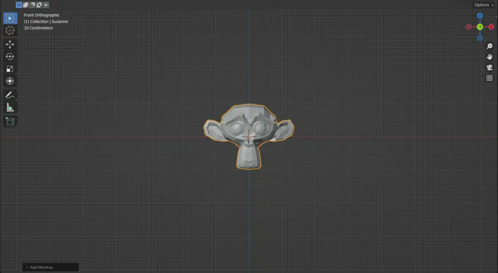
You will switch to the front view if you press one on your number pad. More specifically, you will change to the front orthographic view. This means you can directly look at your model from the front angle without any perspective.
If you press three on the number pad, this will take you to the right orthographic view, and if you press seven on the number pad, it will take you to a top or Bird’s Eye view.
You can position your camera to take renders of your object from these viewpoints by positioning your viewport camera to a 2D view and then using the hotkey Control + Alt + 0 to snap the camera to view.
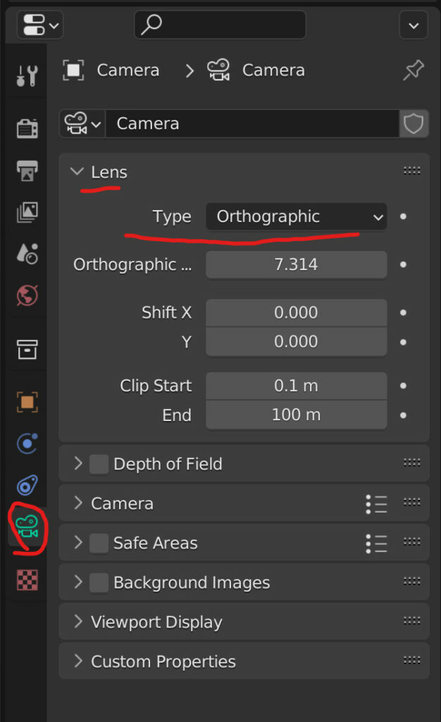
Note, though, that the camera itself will still take the render as if viewed from perspective. To switch the camera to orthographic, select the camera and then Object Data Properties (Properties Panel) > Lens > Type and change the type to orthographic.
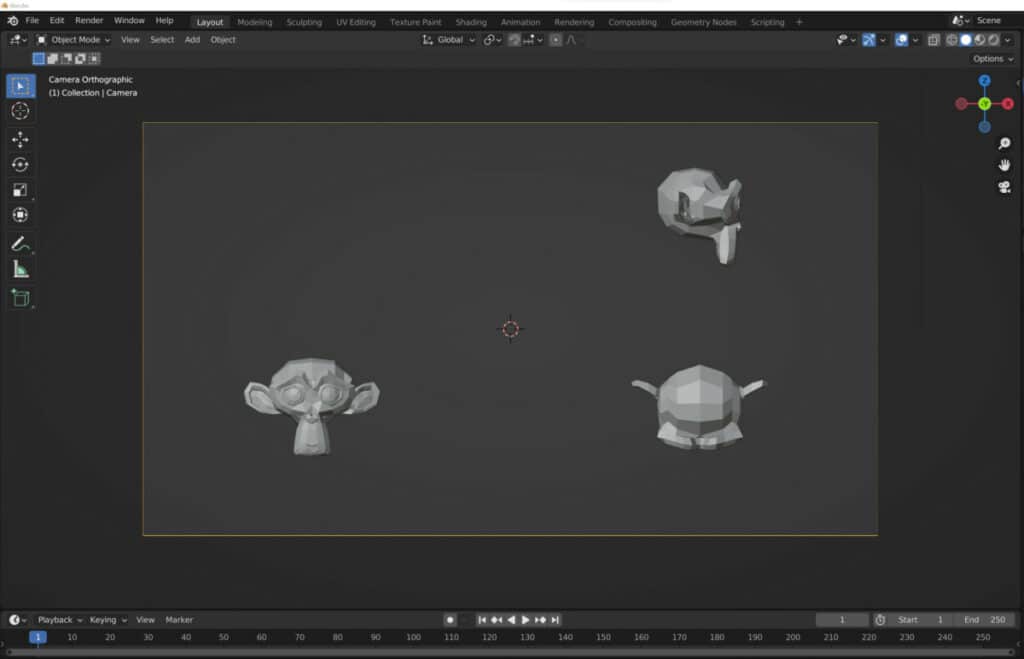
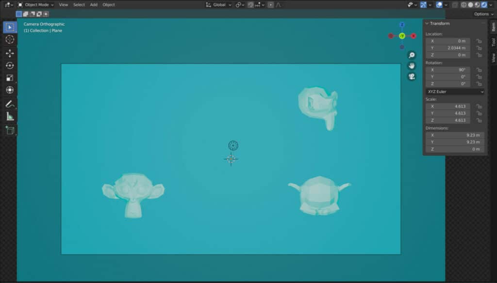
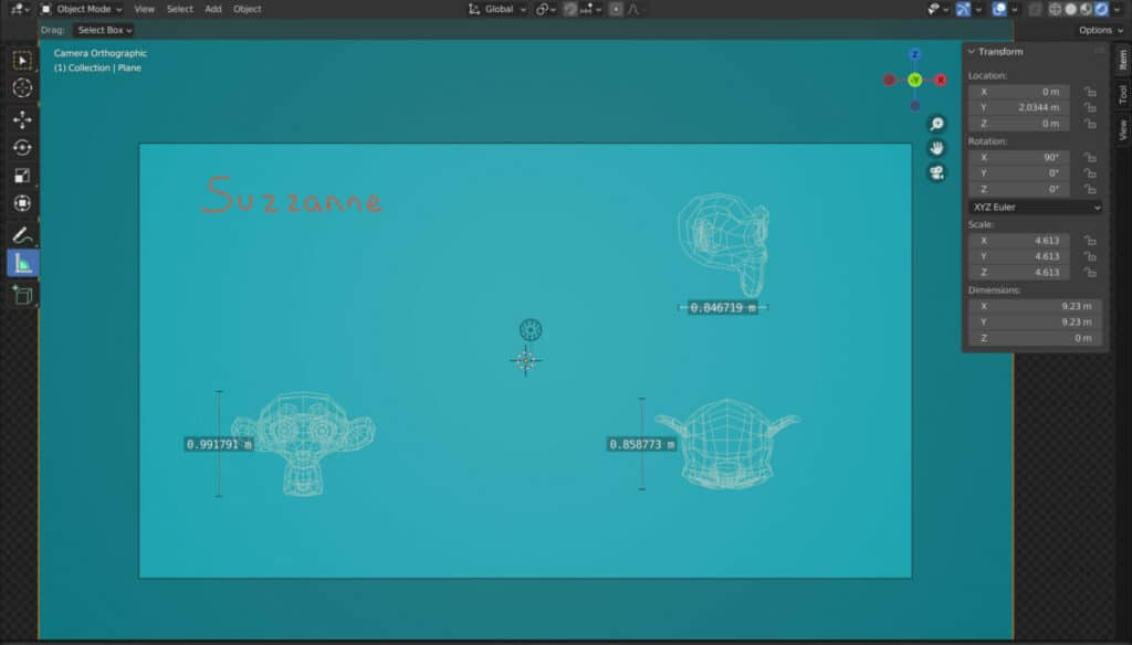
If you want to create renders of your object from multiple views and add them to a blueprint, then a quick and dirty method is to duplicate the object, then rotate it by 90 degrees on a single axis.
This will prevent the need to render multiple times if you can position them within the camera’s bounds, as seen in the image below.
Changing Your Environment Color To Blue
One thing that many blueprints will have in common is that they have blue backgrounds; although this is not strictly a requirement for a technical drawing, there are two ways that you can create this effect in Blender.
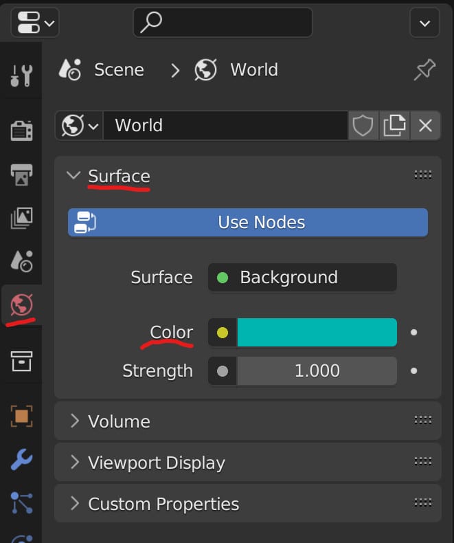
The first method is to change the color of the environment in the viewport. To do this, go to the properties panel and then go World Properties > Surface > Colour and select the color bar to change the color of the environment.
The world color will only change in the rendered view mode, so switch to that viewing mode to preview the effect.
Here you will notice that the world lighting can make the object’s surface difficult to see depending on the light position, so move the light so that it is in between the camera and the objects, pointing directly at the model.
An alternative method is to use a plane object and position it behind the models. You would then go to the materials tab in properties and create a basic Blue material for the plane.
This method prevents the objects from appearing blue, a by-product of using the world lighting to create the blue background.
One Issue used when creating a blue plane is the inclusion of shadows cast from the light source. A blueprint shows the model itself, and there are no shadows because the objects are typically 2D, and the shadows are not necessary to the design.
In Blender, you can turn off shadows based on the material data, as it is the material that defines the behavior of light in the first place.
To turn off cast shadows, create a material for the model you created if you have not already done so. A basic white material will suffice for a Blueprint.
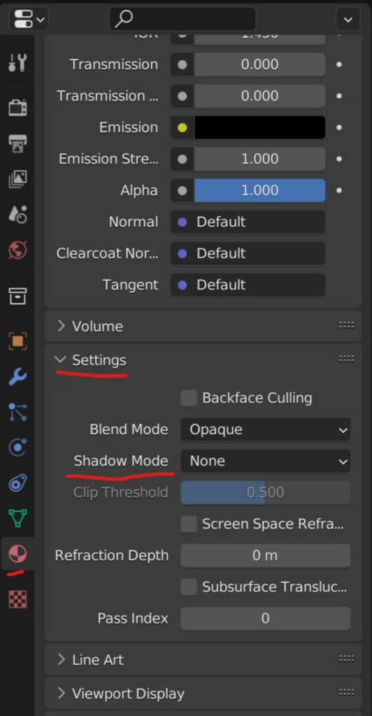
In the materials tab of the properties panel, scroll down until you find the settings section for the active material and open it up.
One of the options listed under settings will be labeled as shadow mode, and the current setting will be opaque.
Select the option to open up a small menu and then select none from the menu to turn off the shadows cast by this material.
Converting Your Objects To Wireframes
Technical drawings do not require the fancy materials and textures you will see on a finished design and instead only require the geometric structure of the model, how it looks, and the various measurements of its shape.
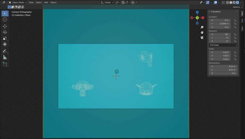
In other words, we want to simplify the drawing as much as possible without losing key details. With 3D Models, the best method for this is to use the wireframe modifier to convert the model into a wireframe with no flat faces but with the model’s shape clearly visible.
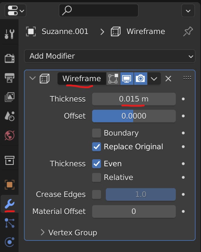
Select your object, go to the properties panel modifiers tab, and add a new modifier to the selected object. From the add modifier menu, select wireframe to add the modifier. Now your model will appear as a wireframe.
To improve the visibility of the lines, you may want to increase the thickness value of the wires. If you have already duplicated the model beforehand, you may be required to repeat the process several times.
Measurements And Annotations
Another important aspect of technical drawings and blueprints is the use of measurements and annotations to describe the various specifications of the model.
In Blender, we are able to both measure our models within the 3D viewport and annotate in the viewport as well. Both tools are found in object mode on the tool shelf, starting with the annotation tool and then the measurement tool below.
It should be noted that neither measurements nor annotations can be rendered, but there are workarounds.
For annotations these can be converted to grease pencil by creating the annotation, pressing F3 on the keyboard, and then typing in convert and selecting convert to grease pencil. However this is an old way to convert and could be removed in the future.
Another alternative for annotations is to use text objects instead, which can be added the same way as any other object type.
With measurements, you cannot render them at all, so the simplest solution is to disable overlays in the 3D viewport by selecting the overlays button in the top corner.
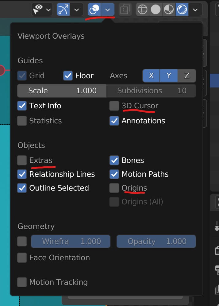
Of course, this will also turn off your annotations if you just press the overlays button, so open up the overlays menu and turn off the 3D cursor, extras, and origin from this menu.
Then open up your screenshot tool, like the snipping tool in windows, and create a screenshot using the camera’s bounds as the image’s border. This way, you can keep both annotations and measurements in your image.
Thanks For Reading The Article
We appreciate you taking the time to read through the article, and we hope you found the information you were looking for. If you are interested in learning more about Blender and how it can be used for more technical workflows like Blueprints and technical drawings, then try some of the articles listed below.