There are a seemingly limitless number of technical and creative applications out there on the market, and it seems as though very conceivable niche or problem has been addressed by at least one new form of software. Some applications, like Blender can address multiple pain points in various projects, but how does it do for technical designs and drawings?
Blender possesses tools that allow artists to create technical drawings within the 3D viewport by using a 2D orthographic viewing mode, which can be done by pressing 1, 3, or 7 on the NumberPad. We can then use the annotate tool to draw lines into the viewport and the measurement tool to create accurate sizing for the design.
This is just one way that we can create technical drawings and designs from within the Blender software. We can make several alterations to this workflow to allow us as artists to create technical drawings on any scale and then immediately begin working on the design itself.
What Is A Technical Drawing?
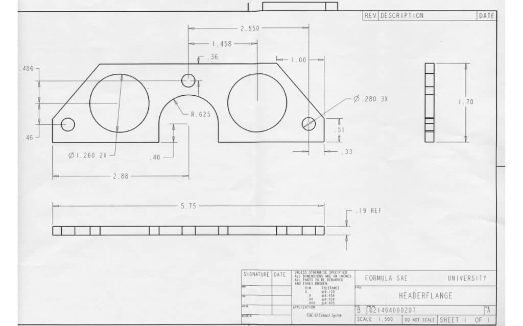
In case you are unsure of what a technical drawing is, it is a representation of a 3D design using images to portray that design from various viewpoints while also displaying other key properties such as the design’s measurements and the parts used to construct it.
Technical drawing has various applications but is most prominently used for manufacturing and architecture.
It is not considered a creative approach to design as much as it is a logical one, as the design in question will likely make its way to the real world and must pass the required specifications to be deemed usable.
Is Blender A Form Of CAD Software?
While Blender can perform similar tasks to CAD software, it is not regarded as CAD software.
CAD software is also computer-aided design and is a type of software built specifically for technical drawing and architectural design.
This means that the tools used by that software will allow us to draw out our designs more easily than in Blender. But that does not mean you can’t use Blender if you choose to,
How To Access 2D Orthographic Views?
To begin creating our technical drawings in Blender, we must first transform the 3D viewport into a 2D space.
This is required because we need to accurately measure our object from the side, front, and top viewpoints.
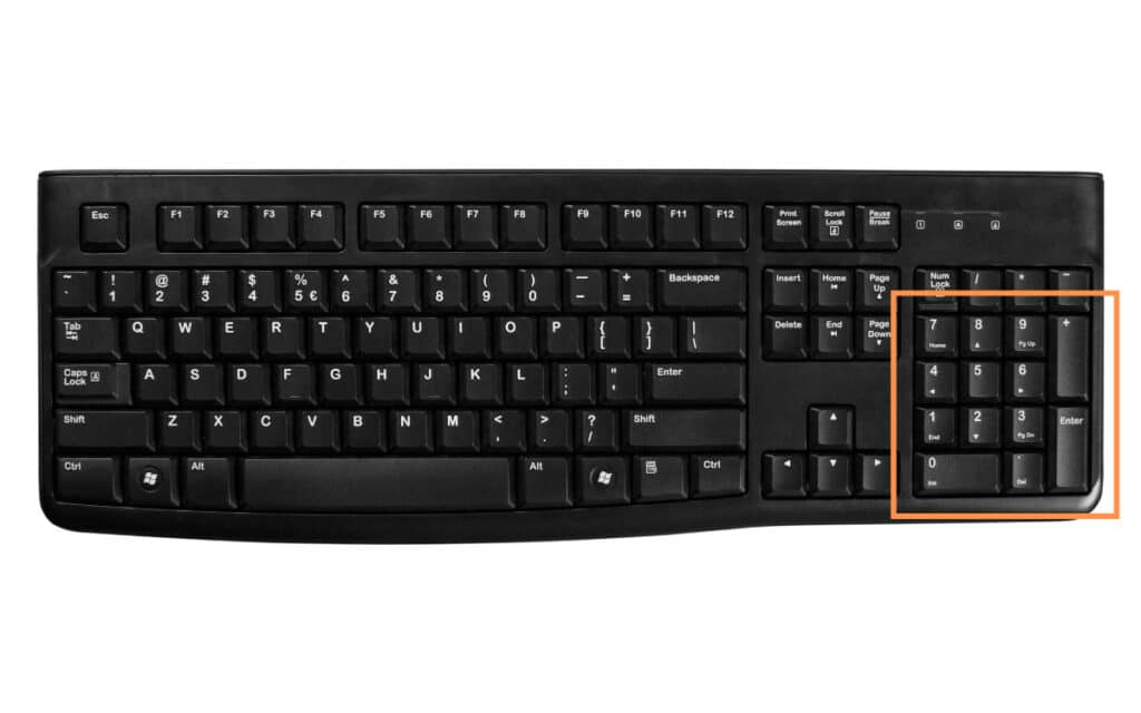
This is easy to do in Blender, especially if you have a full-sized keyboard with a number pad.
- Press 1 on the number pad for front view
- Press 3 on the number pad for side view
- Press 7 on the number pad for top view
If you do not have the number pad available, then you can also use the interactive axis located in the top right-hand corner of the viewport to both navigate the 3D scene and snap to those 2D perspectives.
When you transition your view to one of these 2D options, you will notice that the view type changes from perspective to orthographic, which means the effect of depth and distance in the viewport is mitigated.
We want our technical drawing to be orthographic, so we should not need to do anything here, but if it is still in perspective, you can press 5 on the number pad to switch between perspective and orthographic.
One more way that you can reach these options is to go to the view menu in the 3D viewport and then go to align view, then go to align view to active.
Using The Measurement Tool
The whole point of creating a technical drawing is to define the specifications of a specific design, both in terms of its general shape and the measurements of each part of the model. The more complex the design, the more lines that need to be measured.
In object and edit mode, we have access to the measurement tool, which is invaluable for creating technical drawings of any object.
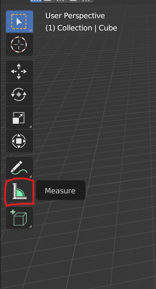
Select the tool from the tool shelf to activate it, and then click and drag in the viewport to create a straight line. Release the button, and Blender will display the value of that line’s length.
If you hold down the control button, you can snap the endpoints of the line. And if you click and drag from the center of a line, you can reposition it to create an angle.
Four Methods To Drawing Lines For Your Technical Drawing
To create your technical drawing, you must 1st always set up your software to view your scene in two dimensions, then ensure that you have a measurement tool to specify any lines or shapes you create.
The next step is to create these shapes, and in Blender, there are numerous ways we could create our drawing.
- One method is to design the model first and then measure that model using the measurement tool and the various 2D views.
- We can also create our lines from scratch by deleting an object in edit mode and then begin adding vertices in our 2D view.
- An alternative to using mesh geometry is to use curves instead, which are a more natural way of generating lines for the drawing.
- If we don’t want to use the 2D viewport, then we can use a 2D animation template and the grease pencil tool to draw our lines onto a 2D plane. This is our RECOMMENDED method.
Thanks For Reading The Article
We appreciate you taking the time to read through the article, and we hope you found the information you were looking for. If you are interested in learning more about the capabilities of the Blender software, then check out some of the articles listed below.