When the concept of geometry nodes was first introduced the idea was to be able to create objects procedurally that could be edited at any point in the process. Fast forward to 2022 and Blender is closer than ever to achieving that goal with the use of various nodes like mesh nodes and utilities.
In the geometry nodes add menu, which you can access with the Shift + A hotkey, you can locate the Mesh nodes that allow you to adjust your geometry in various ways ranging from extruding, to subdividing, to deleting. You can also combine nodes to create more advanced edits such as using extrude mesh and scale elements to inset your geometry.
As geometry nodes continue to develop with each passing version of Blender more nodes will be added to improve the functionality. Now is perhaps the best time to learn how the existing nodes work if you are a beginner at procedural modeling.
How Do Geometry Nodes Work In Blender?
By using geometry nodes to create our models we are replacing a workflow that has existed since the public release of the Blender software 20 years ago and beyond.
What we now know as the standard way of 3D modeling was once the new revelation that allowed artists to visually see their change in real-time using a 3D environment to view their models rather than having to painstakingly code every detail of the object. Yes, 3D modeling once required a very different skill set compared to today.
But now that paradigm looks to shift once again and in a way it feels almost as if we are going back on ourselves.
In other applications like Unreal engine for game design, the use of nodes is also referred to as visual scripting and this is largely accurate.
It offers the same level of flexibility that coding would while operating at a more user-friendly level. But the key reason as to why we now use nodes is because it is procedural.
The term procedural is used to describe something that is infinite in its adaptability. It can be changed at any time and the change can be made at any point of the process.
This means that you are never locked into a specific approach and can make changes to the model as you see fit. This is especially useful when working with clients and you need to make fast changes at their request.
Controlling The Transform Data Of Your Objects
Lets take a look at an example of geometry nodes in effect. We can create what is known as a node tree by going to the geometry nodes workspace, and then clicking the new button in the center to add the tree.
In this tree we have two nodes. The group input stores the original information from the model without any changes from the node tree.
The group output node is the result of all the changes made using the geometry nodes system. In other words they are the start and end points respectively.
We can add nodes in between them to begin making changes to our model. For example we can add a transform node to edit the location, rotation, and scale of the mesh data.
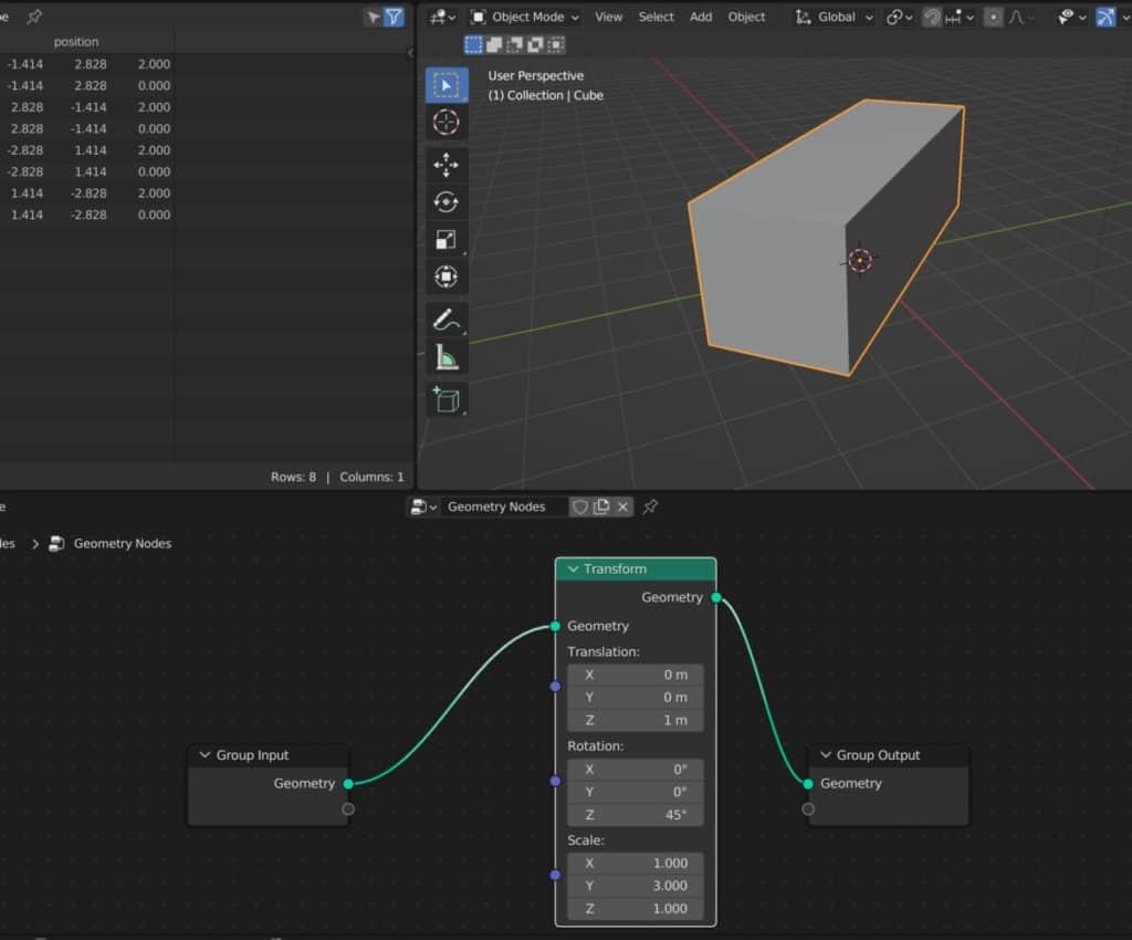
Geometry nodes uses a data flow system where the information flows from left (Group Input) to right (Group Output). The base data from the model is first sent to the transform node and is then edited using the transform properties.
That edited data is then sent from the transform node to the next stage, which is the group output node. The result that you will see in the viewport is the changes made by our transform that were sent to our group output.
This way we are able to perform the most basic of edits to our objects shape, but we can of course go much further than the simple transforms of our model.
If you want to learn more about Blender you can check out our course on Skillshare by clicking the link here and get 1 month free to the entire Skillshare library.
Using Other Objects To Create Booleans For Your Models
There are many ways in which we can use nodes to adjust the shape of our models, and one of the earliest to be introduced was the inclusion of the boolean technique.
A boolean in 3D modelilng is used to describe when we use the geometry of one object to either cut or join with another.
There are two ways that we can create a boolean using other objects. The first way is to use a mesh primitive node to create another shape, while the second is to use the object info node to use the geometry of another object to act as your boolean instance.
For example, lets say we wanted to create a round whole in our cube object. We start by adding the mesh boolean node (not to be confused with the boolean node) and set the type to difference.
We then add a cylinder mesh node and attach it to the second socket, acting as the boolean and cutting away from the model.
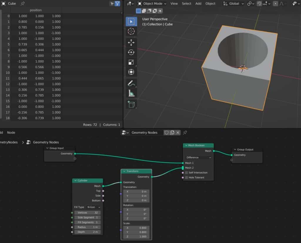
We can still control the booleans’ shape before is reaches the mesh boolean node, such as using a transform to scale down the hole that it eventually creates.
Using an object info node can work in the exact same way. Instead of using a mesh primitive we can use the object info node to act as the boolean instead.
If we take a look at the mesh boolean mode a bit closer, we can see that the second boolean input is elongated.
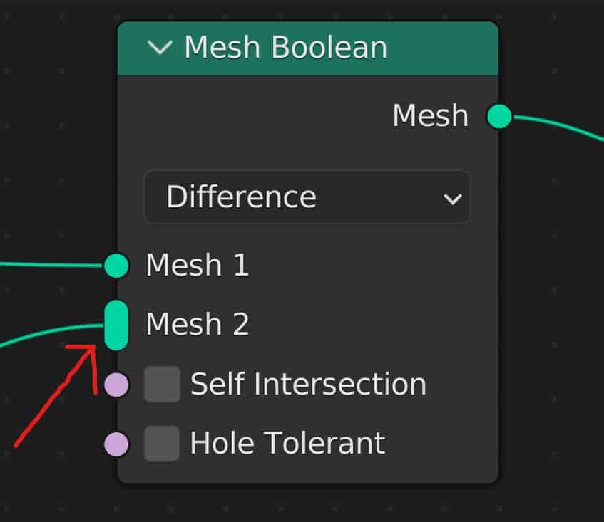
This indicates that the socket can accept multiple connections or noodles and use multiple objects for the boolean.
Some monitors do not come with their own speaker system, so many of us need to find a good pair of speakers for our audio if we don’t want to use headphones. We use these as our daily speaker system as they offer great quality for the price point.
How Fields Affect Object Creation With Geometry Nodes?
The ability to affect our geometry using nodes is based on how geometry nodes are designed to work.
The geometric data typically follows the data flow from left to right in our set up. This means that we start from the group input (Or mesh primitive node) and then edit our geometry at each node until we reach the group output.
However not all our data flows in this direction. Sometimes a node has to go make to the information required to function properly. When data flows from right to left in this way, it is often referred to as a field, or a function used to further manipulate data passing through a particular node.
When you take a look at a node you will see that its sockets are one of two shapes. They are either a circle or a diamond. Some are also a diamond with a dot in the center.
If a socket is the shape of a circle, then it uses traditional data flow to pass information through the node. On the other hand if the socket is a diamond then that node property relies on filed that to recalculate the information used by that node.
If you think about it, how often do see a property with a circular input that you can actually edit in the node?
The sockets that are diamond-shaped but with a dot in the center can use either a field or a fixed value (Data flow).
Taking a look at the boolean node we can see that the boolean sockets are circular, which indicates that we are using fixed values in the form of objects and their geometry.
An example of a node that uses a field could be the separate geometry node. We pass our data through the separate geometry node and then we have two outputs, but to determine what data goes to each output we need to define the selection.
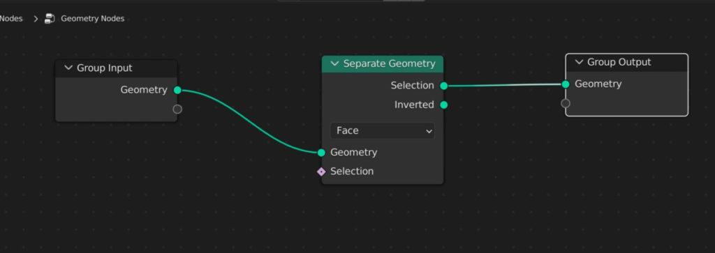
The selection input of the separate geometry node can use either a fixed value or a field to define the selection output.
We can also use an attribute node to further distinguish the information that is being used by the selection input.
The position node calls the position attributes of our vertex data, so we can add the position node and connect it to our selection input to call that position data for the separate geometry node.
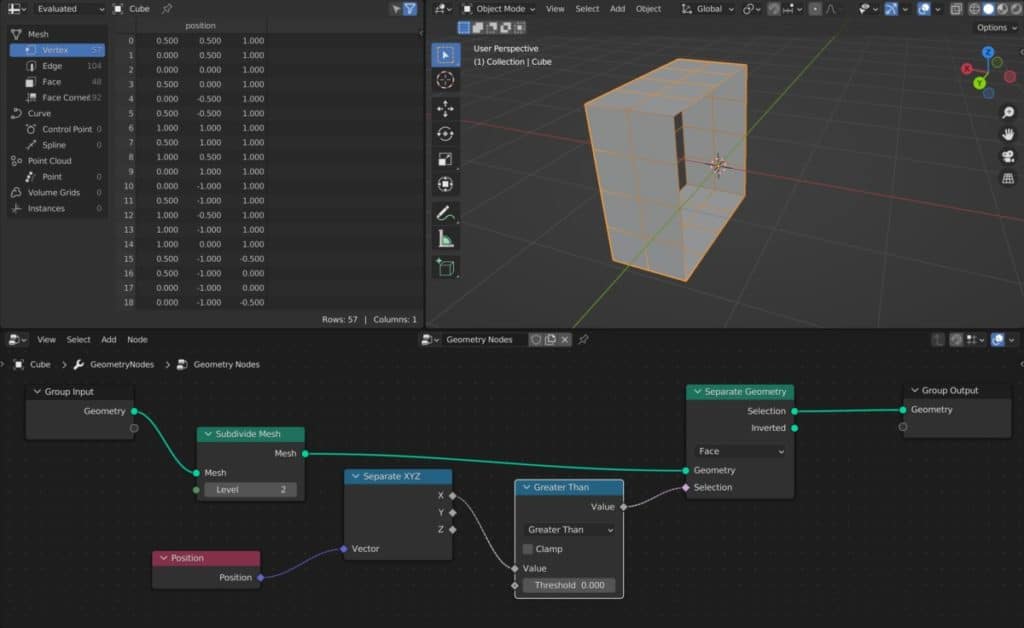
A basic example here is to use the position attribute to define the selection so that we can determine which vertices are going to fall in which category. We can then define this by using a separate XYZ node and choosing one of the three channels.
Once the channel or axes has been defined, we can then use a utility’s node like a math node to define the formula that blender is going to use for the separation. In our example, we could choose a greater than node and set the threshold to 0.
By doing this we create a scenario where Blender will find the value of each vertex on a specific axis and if that value is greater than zero then it will be assigned the selection output and if it is not greater than zero then it will be assigned the inverted output.
Below is an example of this node setup in effect on a model. The separate geometry node uses the field that is generated from the selection inputs to calculate how the selection is going to be separated.
Examples Of Nodes That Are Used For Modelling Our Geometry
With each passing update, there are more and more tools added to the geometry node system used for modeling our geometry. Let’s take a look at some of the traditional things that we could normally do in 3D modeling and how we can perform those same actions using geometry nodes.
How To Extrude Our Geometry
One of the most basic modelling tools that 3D artists learn early on is the ability to extrude out new geometry from existing faces. In Blender there are many different forms of extrusion and locations to find the extrude tool.
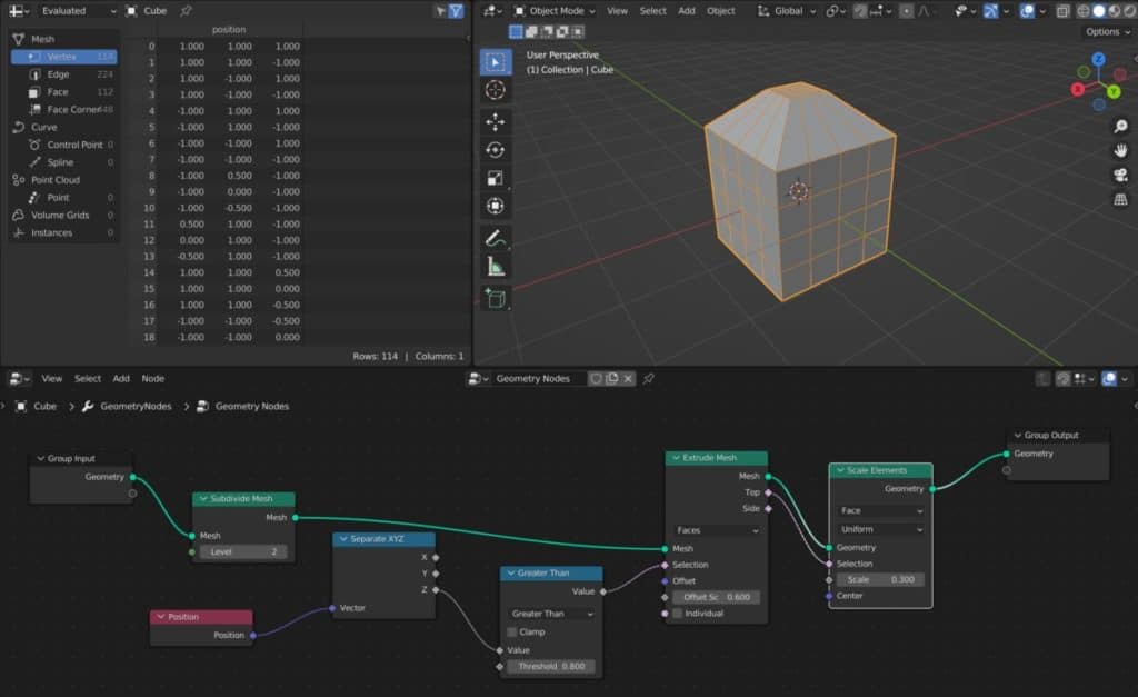
In geometry nodes we can extrude our mesh by using the extrude mesh node. Like many nodes that affect our geometry directly, we can use the selection input to define which faces are going to be extruded by this node.
Below is an example of a set up where a part of our geometry has been extruded, and then the top face has been scaled down to create a hut.
Creating An Inset
In traditional 3D modelling there are two ways that we can inset our faces. The first method is to use the inset tool itself from either the tool shelf or by using the hotkey.
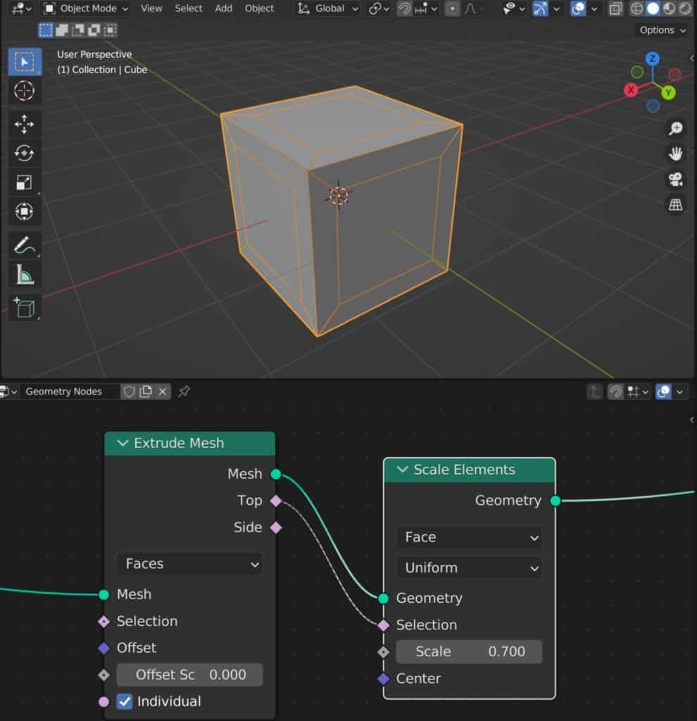
The second method for creating an inset is to use the extrude tool to create the geometry and then use the scale tool to inset it from the same location.
In geometry nodes we need to mimic the second method by first creating an extrude mesh node and then setting the offset scale value to 0. Then we need to add a scale elements node and define the selection to the top faces generated defined by the extrusion which can be seen in the image below.
Subdividing To Add Geometry
Whenever we lack the geometry density required to edit our model successfully, we need to add more geometry to the model as a whole.
There are a couple of nodes that we can use to add density to our geometry, the most basic of which is the subdivide mesh node.
This works in much the same way as the subdivide tool does in the viewport. Simply add the node into your setup and then increase the level count to increase the geometry density.
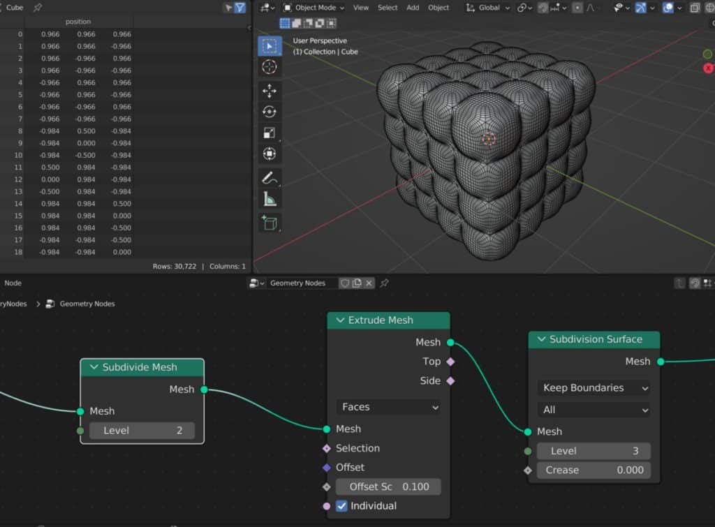
The key difference here though is that it uses the same formula as the subdivision surface modifier, multiplying each face by 4 with each added level.
The alternate method is to use the subdivision surface node instead, which uses the same base formula but has a couple of additional options for smoothing.
Below is an example of a surface pattern created by using the subdivide mesh and subdivision surface nodes.
Deleting Unwanted Geometry
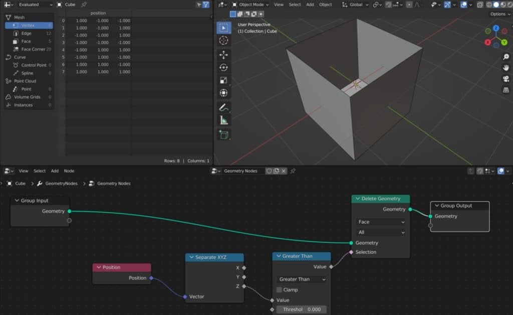
Just as important as the ability to add geometry is the ability to remove it. We have already seen the ability to separate our geometry into separate channels, but we also have the ability to delete our geometry entirely with the help of the delete geometry nodes.
This works in a very similar manner to the separate geometry node, with the main difference being that we have only one output which contains data of the geometry that has not been deleted. We can also define the types of geometry that we wish to delete using this node.
Below is an example where we have used the delete geometry node and its selection input to delete the top face of the cube, creating a box.
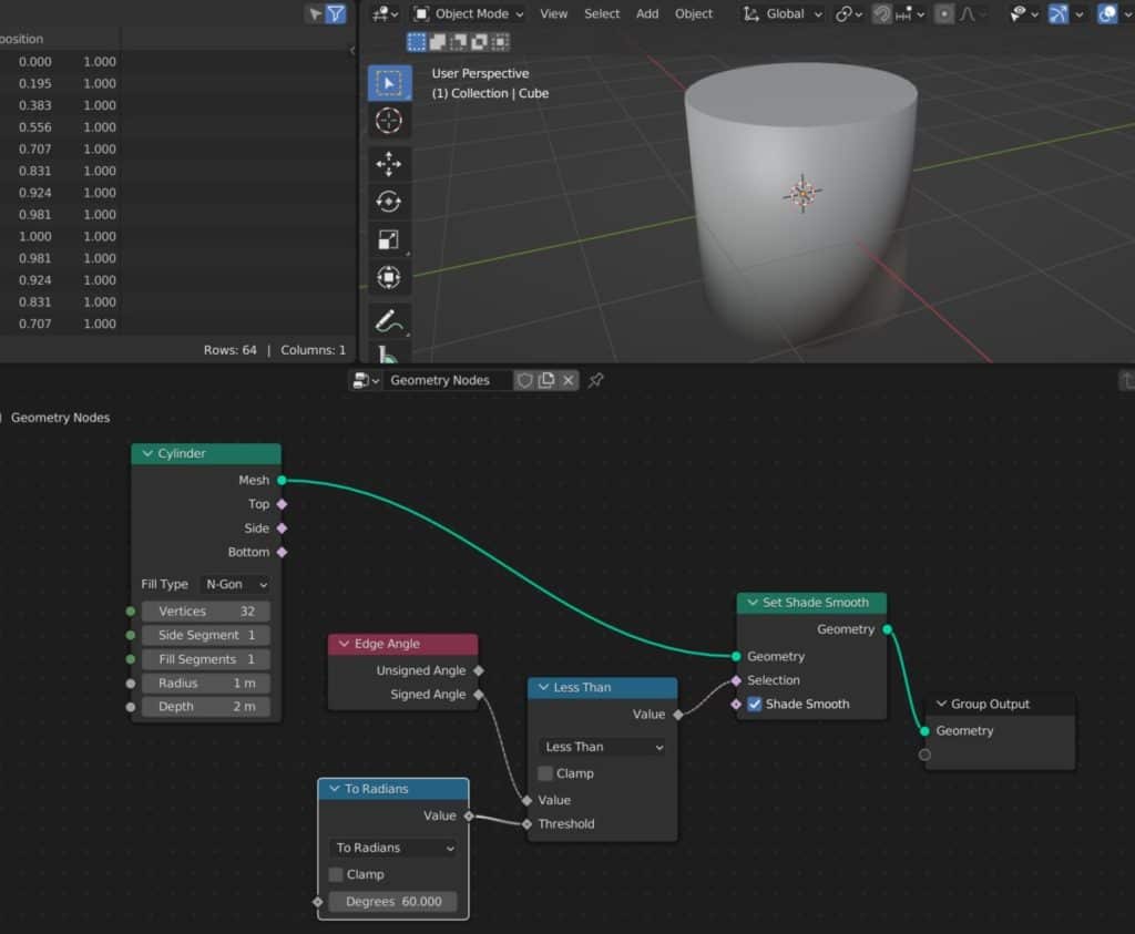
Adding Smooth Shading
A common tool used by artists the smooth shading tool, which changes the shade type of our geometry from flat shading to smooth shading.
This remains equally important in geometry nodes as we don’t want all of our geometry to be on display in the render, only the structure that it creates.
Below is an example of a cylinder that has been shaded smooth.
Thanks For Reading The Article
We appreciate you taking the time to read through the article and we hope that you have been able to locate the information that you were looking for. Below we have compiled a list of additional topics that are available for you to view and learn more about Blender.
-
Edge Loops for Hard Surfaces in Blender
Utilizing edge loops for defining crisp hard surface details in Blender.
-
Blender Kitbashing: Complex Shapes Made Easy
Simplifying complex shape creation with Blender’s kitbashing approach.