The idea of introducing geometry nodes was to create a new procedural workflow that could replace much of the existing methods for traditional 3D modeling. Perhaps the most challenging aspect of all is being able to define what geometry you need to edit rather than affecting the model as a whole.
To define what geometry you want your nodes to affect, you will need to make use of the selection input that is used by many nodes in Blender. With this input, you can call what geometry you wish to use based on pre-built attributes such as the index and position attributes for vertices, or the normal value for faces.
Once you are able to grasp the methods behind geometry selection, you will find that using geometry nodes is far more powerful than simply affecting the entire model. There are also many examples where we can define our selection to change a node’s effect on the model in various ways.
Selecting Other Objects By Using The Object Info Node And Mesh Primitives
Using Geometry Nodes we have the ability to select the geometry of our current objects, primitive objects generated by a mesh primitive node, other objects in our scene, and even entire collections.
The way in which we select and then use these varies in each case with the simplest example being the ability to select an object using either a mesh primitive or another model in our scene.
Let’s start with adding a mesh primitive object. In Blender, we have the ability to add primitive models using nodes to either edit the base geometry of our model or even replace the base geometry entirely.
Below is an example where a UV sphere has been added to a new geometry node setup. This node replaces the connection between the group input and group output nodes and therefore the output is the data received from that UV sphere node.
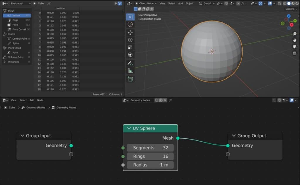
The key advantage to using a mesh primitive in this way is that we can edit the base parameters procedurally from the respective node. In the case of the UV sphere, we can continue to edit its radius, rings, and segments even after creation by using the node method.
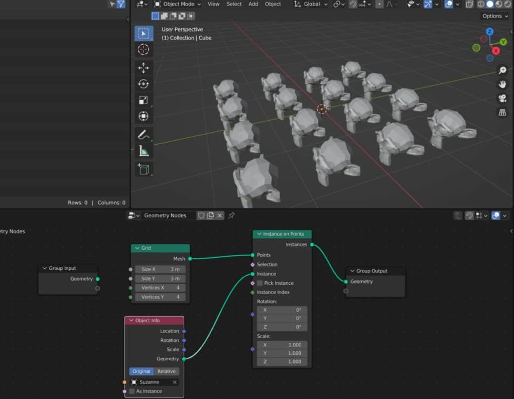
We can also use information from the other objects in our scene in some scenarios like instancing out objects to the points generated by the current model.
In this example, we have a grid acting as the base geometry, and then we convert the grid into instances. The object info node can then be used to assign an object to each point, with each iteration acting as an instance of that geometry.
Can I Use An Entire Collection As My Selection For Instancing?
Not only are we able to reference a single object for instancing, but we are also able to reference an entire collection with the collection info node.
This works in a very similar manner to when we are using the object info node and is attached to the same point in the node tree.
The key difference between the object info and collection info nodes is that you will need to ensure that all the boxes are ticked for collection info including the pick instance option.
With these options enabled Blender will choose a single object from your collection to act as an instance rather than the whole collection at each point.
An example where you may want an entire collection may though maybe when you are creating different shades of grass and position them to the same location.
If you want to learn more about Blender you can check out our course on Skillshare by clicking the link here and get 1 month free to the entire Skillshare library.
Using Field Nodes To Control My Selection
The ability to select our geometry is a bit more challenging than referencing other objects in our scene as the quantity of our selection is typically much greater.
This is perhaps the one aspect of geometry nodes that will always be more difficult with traditional modeling.
In the 3D viewport selection is simple, you press the TAB key to enter edit mode, select the type of geometry that you want to select from vertex, edge, or face, and the click to select.
Selecting multiple elements like faces can be done by using more advanced methods of selection like circle or box select, as well as using the secondary keys (Shift, Control, Alt).
There are as many tools for selecting your geometry as there are for editing your geometry in the 3D viewport.
So by traditional means, selection is very easy in Blender, but in geometry nodes, this is not necessarily the case.
To define your selection, you are normally going to need to pay attention to the selection input that is found on many of the geometry nodes.
The large majority of nodes that edit your actual topology in some way will possess the selection input, which will allow you to use a field to define your selection.
What Are Fields?
If you have not heard of the term field before, this is used to describe a function where the data flows from right to left.
Typical data flow in geometry nodes goes from left to right, starting with the group input and then finishing at the group output.
A field is where we start from a specific node and then we go backward to gather the data that can be used to manipulate that node.
Using A Field With Position Data
A typical example would be to use the set position node to define the position data of our selected geometry.
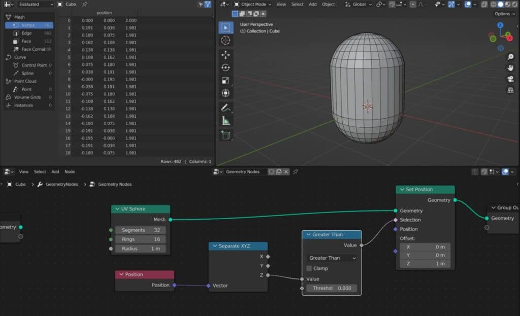
In our example, we create a UV sphere, and then we use the set position node to define where our geometry is going to go.
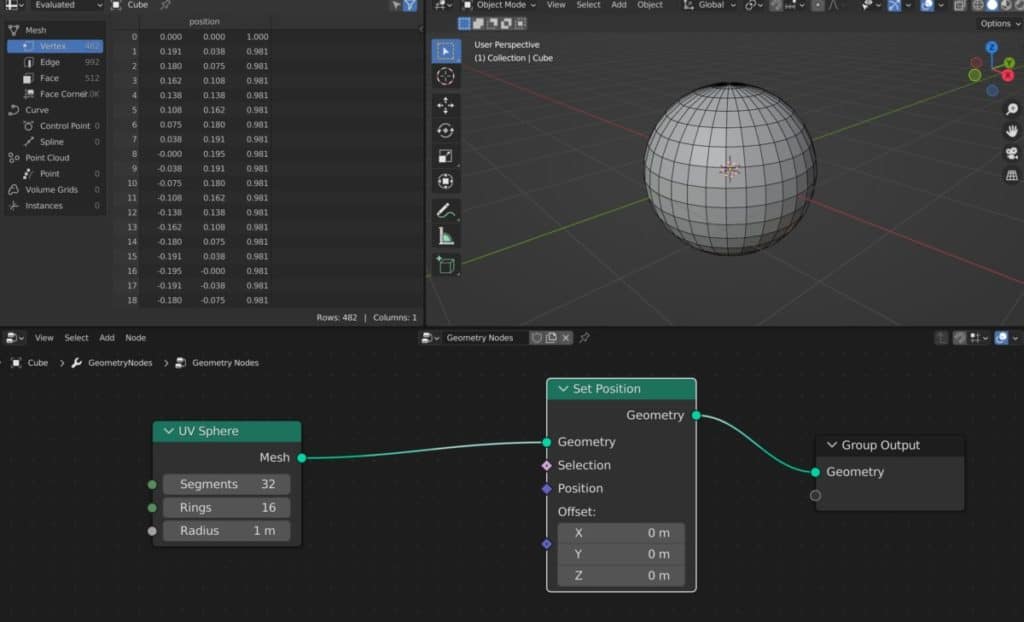
We want to set position no to only affect the vertices on the top half of our UV sphere. To do this, we’re going to need to define at that top half as our selection.
First, add a Position node. The position is an attribute that is associated to the vertex elements of our model.
Connect the Position node to the selection, which will call the position data for the selection itself. To define the selection we need to use a combination of maths and other utility nodes. If we want to focus our selection on the top half of our UV sphere, then we are working on the Z axis and so we will need to isolate the channel for the position attribute.
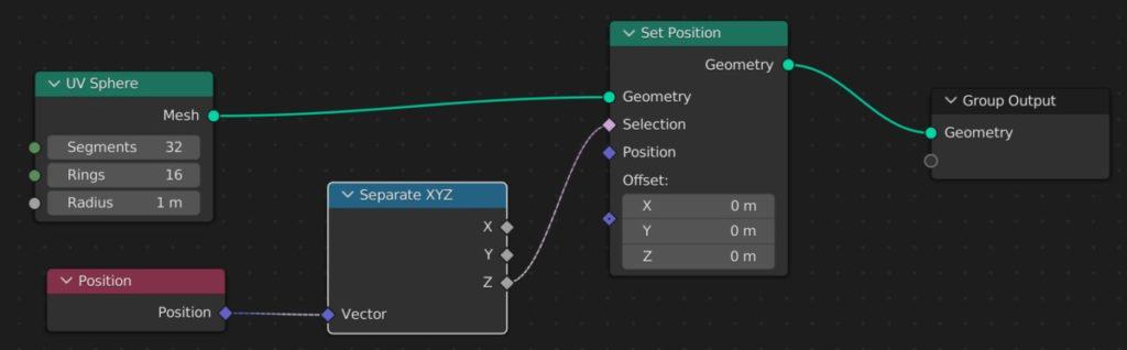
The best way to achieve this is to introduce a separate XYZ node and then use the Z channel from this node as your selection.
Then we need to tell Blender the formula that we need it to use to define the selection, which can be done by using a math node.
If we use a greater than node then set it to 0, then all the vertices with a Z value higher than 0 will be affected by the set position node, allowing us to edit the selection with the offset values.
This will now allow us to control the selection using the field that we have created, and then manipulate the selection using the set position node.
Some monitors do not come with their own speaker system, so many of us need to find a good pair of speakers for our audio if we don’t want to use headphones. We use these as our daily speaker system as they offer great quality for the price point.
How To Randomly Select Our Geometry In Geometry Nodes?
We can take things a step further and add some randomization to the selection of our elements to create more abstract effects.
For example, let’s say we want to subdivide a cube and then extrude a random selection of faces on that cube. We can use the subdivide mesh node to increase our geometry and then the extrude mesh node to extrude it.
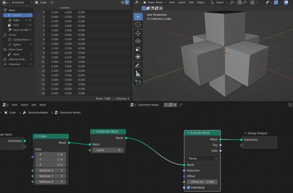
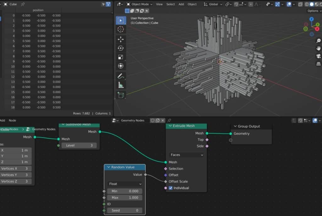
However, without guidance, all the faces will be extruded at the same level. To add some variation to it we need to use a random value node.
Once this is added it creates that variation that we have been looking for. From here we can adjust the values to whatever we need.
Thanks For Reading The Article
We appreciate you taking the time to read through the article and we hope that you have been able to locate the information that you were looking for. Below we have compiled a list of additional topics that are available for you to view and learn more about Blender.
-
Bevel & Chamfer: Blender’s Edge Mastery
Mastering the application of bevels and chamfers for sharp edges in Blender.
-
Non-Destructive Workflow in Blender
Embracing a non-destructive workflow for flexible modeling in Blender.
-
Detailing with Booleans: Blender Techniques
Incorporating Boolean operations for intricate detailing in Blender.