There are a near-limitless number of ways that we can control our geometry using the geometry nodes system including the ability to reassign, rotate, and redistribute the various points of our mesh geometry. With many tools, we can take this control to greater heights by using vertex groups.
A vertex group becomes a custom attribute in geometry nodes which when created can be found in the points domain of the spreadsheet. Connecting a parameter to a group input node will then allow you to call that vertex group by pressing the cross button in the modifier. It can then be used to control where a node affects a model, like isolating the top face of a cube.
There are other ways that we can use vertex groups in our node-setups as well, including using said groups to distribute instanced geometry or defining the areas of the model that are extruded.
The Traditional Way Of Assigning And Selecting Vertex Groups
In order to use vertex groups in geometry nodes, we first need to assign them to our objects. If you do not know how to assign geometry to a vertex group, it can be done in two simple steps.
The 1st step is to go into edit mode for your object and then select the vertices that you want to have as your vertex group. In our example below we have selected the top four vertices of our cube to be assigned.
The 2nd step will be to assign our selection to a new vertex group, which we can do so by going to the object data tab in the properties panel, which has the icon of an upside down triangle.
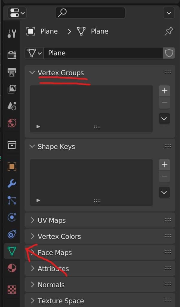
The first drop down in this tab will display the vertex groups assigned to the current mesh data. It should be empty if you do not have any other vertex groups already. Click on the add button to ad a new vertex group to the menu.
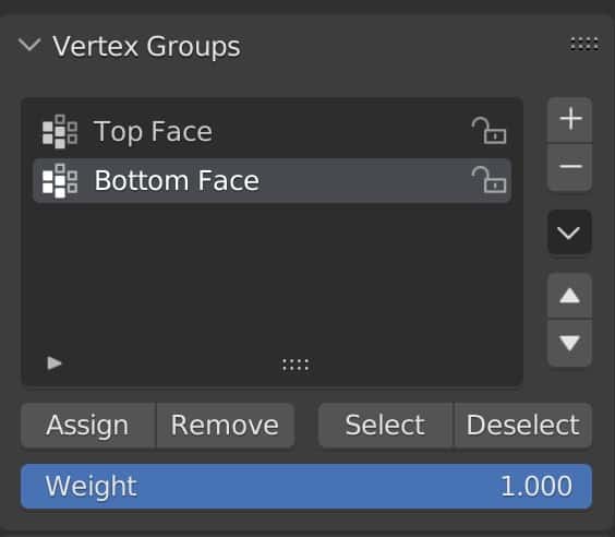
Double left click on the name in the list to rename the vertex group that you created. For our example we are going to name it as top face.
You should still be in edit mode at this point and so you will see four options directly below the menu to either Assign, Remove, Select, or Deselect.
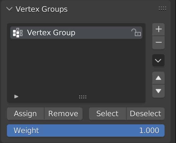
If you choose the assign option then all of the selected geometry will be assigned to that vertex group. Note that we can create as many vertex groups as we need, and that a vertex can be assigned to multiple vertex groups.
Remove will subtract our selected geometry from a vertex group if it was previously assigned, while the select and deselect option allow us to select a vertex group with a single button press.
Make sure to press the assign button with your geometry selected to connect them to the vertex group that you made.
For our example we are going to select the vertices at the bottom of our cube, press the plus button and then rename the new group as bottom face, then click the assign button. This will give us two vertex groups to work with.
Vertex groups can be used with many other tools in Blender such as certain modifiers. For example, you can use the bevel modifier and restrict the bevel to the vertex group.
Can We Create Vertex Groups Using Geometry Nodes Instead?
When using geometry nodes, there are various ways in which we can define our selection for our node systems. Many of our nodes will have a selection input that will allow us to dictate what part of the model is affected by that specific node.
We also have the ability to assign special values known as ID values to our individual points, edges or faces. However, at the time of writing, there is no known node that is going to allow us to create a vertex group directly depending on a defined selection.
This is not necessarily a bad thing, however, as it’s very easy to create our vertex group using traditional methods of selection in the 3D viewports, and then begin using that vertex group as an attribute in blender anyway.
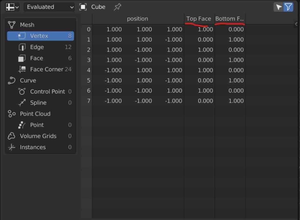
Once we have created a vertex group using traditional methods, that vertex group will be displayed under the vertex domain in our spreadsheet. So there is really any need or requirement to be able to create that vertex group in the node system itself.
Also note that if we were to create a vertex group using a specific set of nodes within our geometry node system, then that vertex group would only be usable within that geometry nodes set up as it would be based off of the geometry created by that node system.
This is another reason why the current setup is so beneficial to just create vertex groups traditionally so that we have the flexibility of using those vertex groups outside of the geometry node setup.
If you want to learn more about Blender you can check out our course on Skillshare by clicking the link here and get 1 month free to the entire Skillshare library.
Using Your Vertex Groups Through Geometry Nodes
In Blender we are able to call out attributes when using specific nodes in our geometry nodes system and this includes custom attributes that we create such as vertex groups.
To recap, a custom attribute is a form of data that is defined by the user rather than being predefined in blender. For example, the index value of each individual vertex is predefined and will already be visible even before you create a new geometry node system in the spreadsheet.
A vertex group on the other hand, is something that you yourself as the user creates, which is why it is considered a custom attribute that does not display in the spreadsheet until it is created and defined.
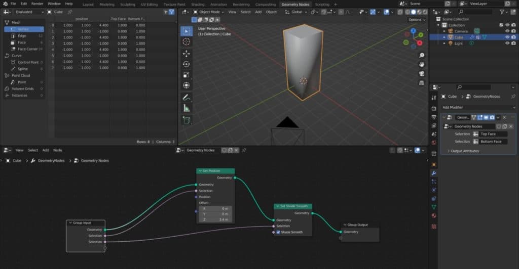
Let’s now take a look at a couple of ways in which we can use vertex groups in geometry nodes. The first example is going to be defining which of our vertices are going to be affected by a set position node.
We can see a very basic setup where the set position node is being used to manipulate the positioning of the individual points.
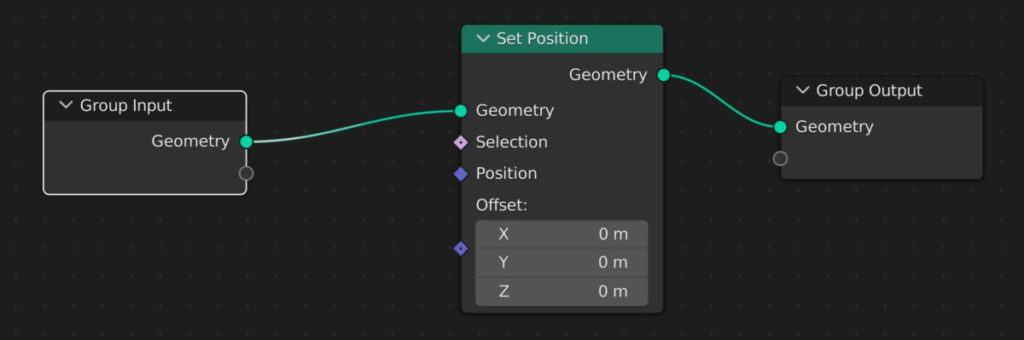
So long as the set up is not defined by any selection, the entire model is going to be manipulated by the offset value. We are going to want to define the vertex group for use by the set position node so that only those vertices are affected.
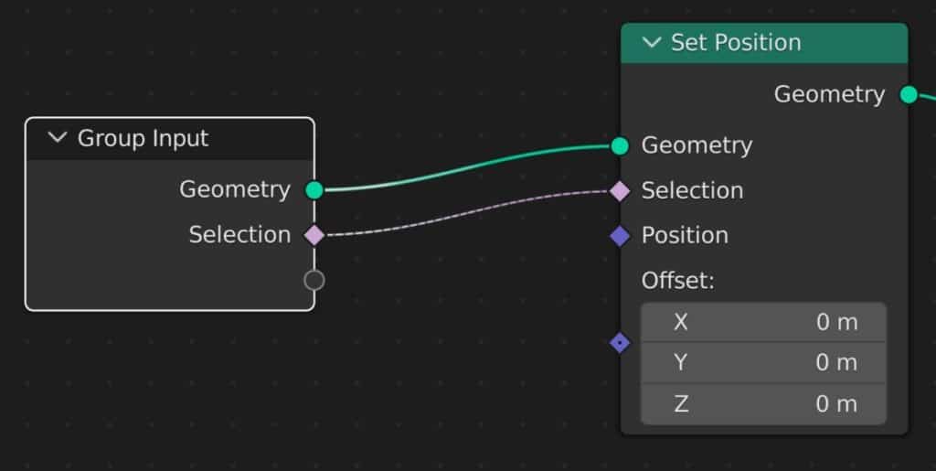
The easiest way to do this is to click and drag your selection input from a set position node and connect it to the group input node. This will expose the selection as a parameter in the geometry nodes modifier.
For the parameter in the modifier, you will notice that there is a cross button next to a numerical value. At the moment, because we are using selection data, that numerical value is either going to be zero or one and does not allow us to do anything specific.
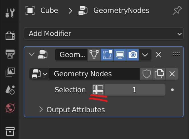
So instead what we are going to do is click on that cross button and this is going to allow us to define our selection with an attribute.
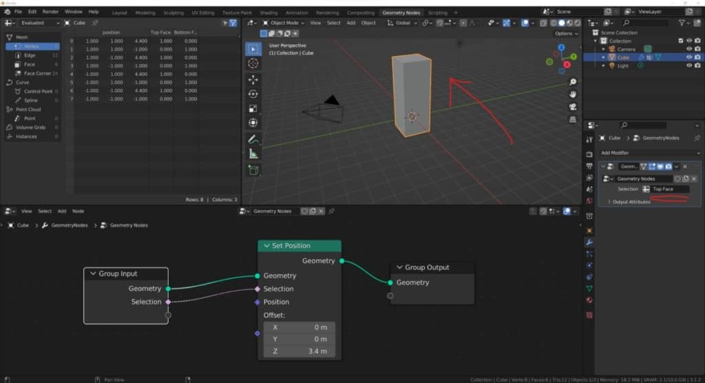
When you click on the empty box that appears in place of the number, you will get a list of all of the current attributes that are assigned to the various domains of your model. At the bottom of this list will likely be the vertex groups that you have created.
In our example, we are going to select the top face attribute. If we now attempt to manipulate the offset values of the set position node, you will notice that only the vertices that were assigned to that top face have been manipulated by the set position node.
We can change the defined attributes at anytime by returning to that parameter in our modifier, clicking on it, and then selecting another attributes from that menu. For example, we could select the bottom face attributes and then when we manipulate the set position node it will affect the bottom vertices instead.
Another example of using vertex groups with our geometry node system is to determine which parts of our model are smooth shaded. For example, we could add a set shade smooth node to the set up, and then connect our selection input to another empty socket of the group input node. Go to the modifier, and then click on that cross button to enable attribute selection.
We can then choose the custom vertex group that we want to use to define which of our vertices are going to be given smooth shading. As you can see in the example below.
Not all nodes will work with vertex groups in the same way, so it’s important to experiment with the various nodes and how they can be influenced by our vertex groups.
When sculpting or texture painting in Blender the best method is to always use a graphics tablet. But these come at many different price points and forms. If you want to get started with sculpting using a graphics tablet then we recommend this as your starting point. It served us well for over 4 years before we upgraded to a more expensive tablet ourselves.
What Else Can You Do With Vertex Groups And Geometry Nodes?
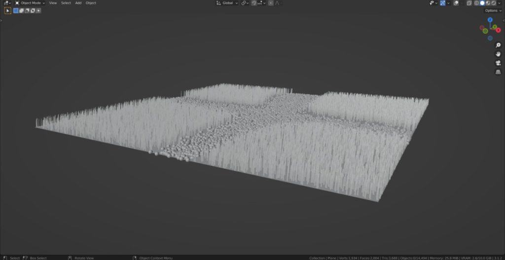
Another way that we can use vertex groups in geometry nodes is to define the positioning, for instance geometry. For example, let’s say I wanted to create a plane with grass and rocks. I want to create a pathway that is made out of the rocks going through my geometry.
The rest of the model is going to be the grass. I can use my vertex groups to determine the location of each set of instance geometry. Let’s take a look at this as an example.
The base set up here is going to start with a plain object that has been subdivided in the 3D viewport a total of 100 times to give it plenty of density.
The assets that I will be using for my example are simple primitive objects that are just undergone a slight change. For example, my grass asset is just a plane that has been rotated and had a couple of loop cuts added to it. While the rock asset, on the other hand, is simply a Ico sphere.
Another way of creating a vertex group from what we have already discussed is to use weight painting in blender.
If you do not have any vertex groups, then you can go into weight painting mode and begin to paint onto the surface of your plane object. When you are finished with your white painting, a new vertex group will be added which you can then rename appropriately.
For example, we can create a couple of paths on our plane using weight painting and then name the generated vertex group as rocks.
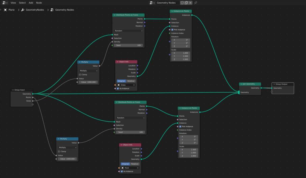
We can then use our instance on points node as well as our distributes points the faces nodes to define our instancing where we can position our rock vertex group. You can see an example of this with the setup that we have generated below.
Thanks For Reading The Article
We appreciate you taking the time to read through the article and we hope that you have been able to locate the information that you were looking for. Below we have compiled a list of additional topics that are available for you to view and learn more about Blender.
-
Blender Proportional Editing: Shape Control
Controlling mesh deformation with Blender’s Proportional Editing tool.
-
Simplify Meshes: Blender’s Quick Tools
Quick and effective methods for simplifying complex meshes in Blender.
-
Efficient Modelling: Blender Modifiers Guide
Streamlining modeling workflows with Blender’s powerful modifiers.