If you want to set up very basic materials in Blender, then you only need to use the materials tab in the properties panel in order to create those simple materials. But if you want more control over your materials and how they are applied to your model, then you will need to learn how to use the node editor. If you have not used the node editor
The node editor is a tree of nodes that branch out horizontally from a root node referred to as the output. Nodes are visually small boxes that store specific data and parameters that affect the end result. Nodes are connected together via noodles and the order of the nodes also plays a role in the final output.
It can be very confusing to someone who has not used a node system before, and there are two more node systems in Blender for composting and geometry that follow the same principles. So we will cover all the need-to-know stuff about how a node system is supposed to work so that you can get comfortable with setting up your own materials with the node editor.
How Does The Node Editor Output The Material?
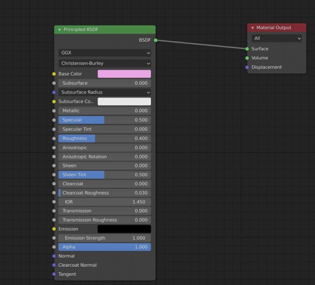
All node-setups node to finish with an output node, and in the case of the material, a material output node is required. All data received from other connected nodes eventually finds its way to the material output node, which then transmits that data to all objects using that material.
In most materials, the number one node type that is connected to the material output is going to be your primary shader. A shader is a type of node that assigns the properties of the material that allow it to behave in certain ways when hit by a source of light.
For example, reducing the roughness of a shader node to 0 will make the surface of a material clear and reflective. While the base color attribute assigns a default color to the material, like pink, blue, or orange. Different shader nodes have different attributes that can be used to control the material.
The shader to learn is the principled shader, which is used in most PBR quality materials as the primary shader that is often directly connected. Other shaders that you can use include the glass shader, which can be used to start creating glass-like materials, or the transparent shader, which makes a material transparent.
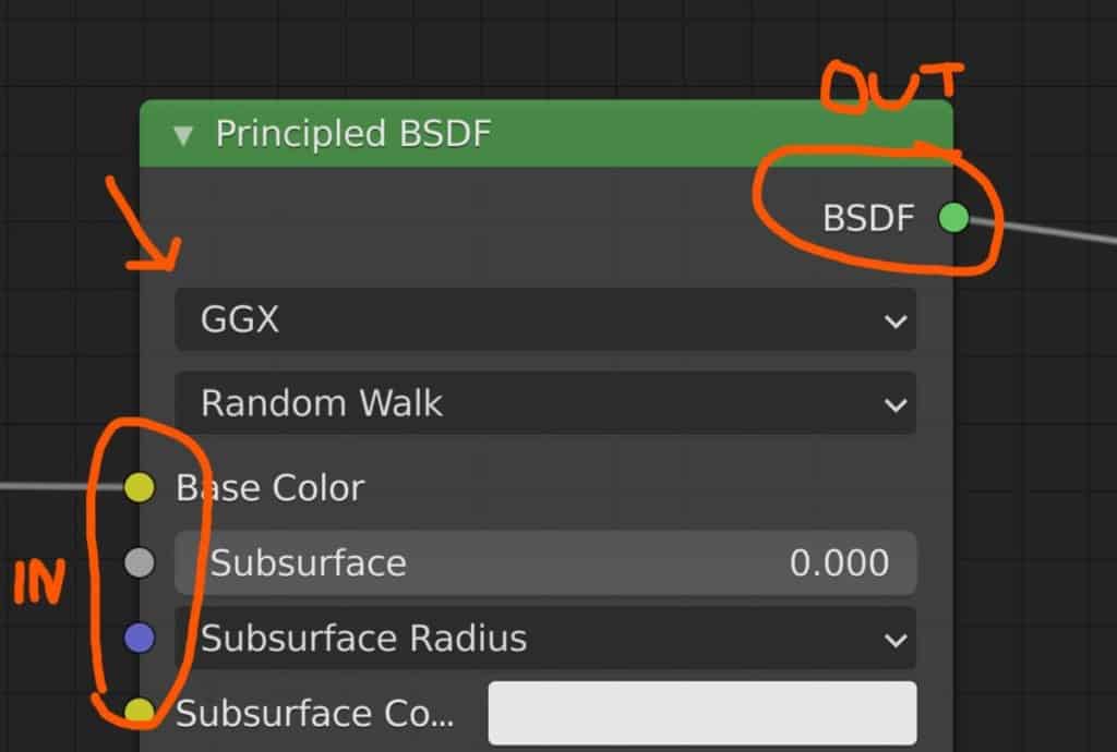
Nodes will have a selection of outputs and inputs on either side of the node. An input brings in data from other nodes, while an output sends that data to the next node in the tree.
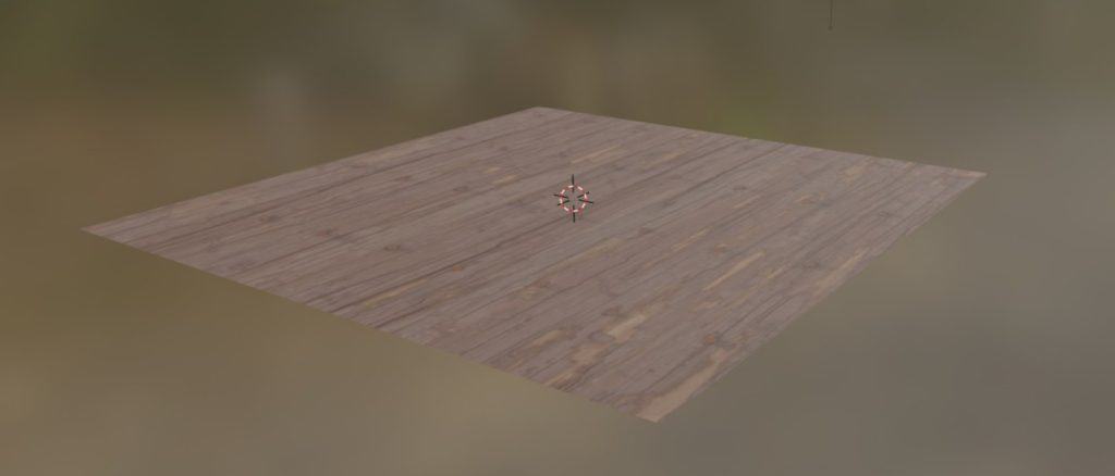
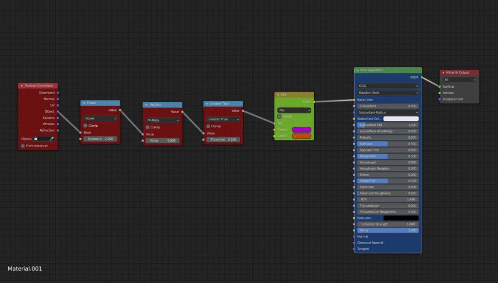
Below is a simple setup where we have a material with a texture that has been mapped to it. This is a very common set up used for many materials and acts as the base for more complex ones. The data is transferred from left to right, always finishing with the material output node.
Noodles are used to connect the nodes together, and you do so by connecting the output of one node to the input of another. Note that you cannot connect an input to an input, or an output to output. A node can be connected to multiple other nodes spending on the number of sockets that are on either side.
Another rule is that output can be sent to multiple inputs, either from a single node or multiple nodes. For example, you can connect the color output of the image texture to the base color and subsurface color inputs on the shader if you want. However, an input can only take data from a single output, as it needs to be able to process that data for the node.
Adding Nodes
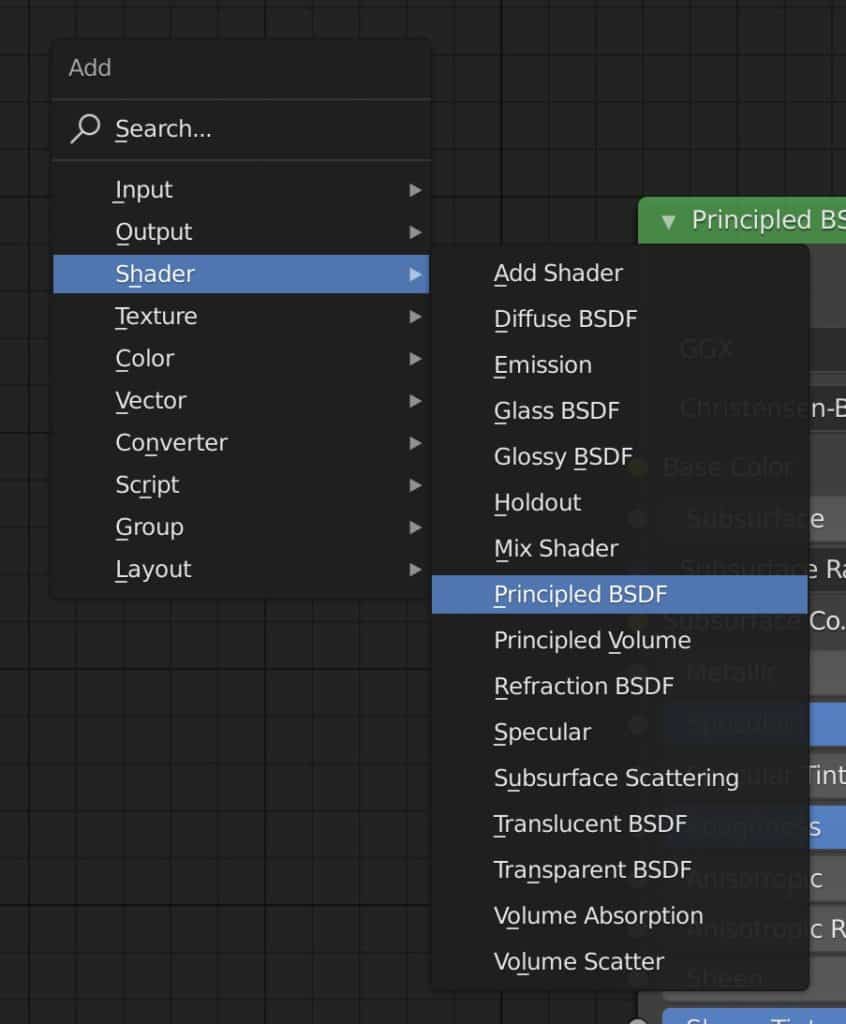
Adding a new node is similar to adding a new object in the viewport, as its simply a matter of going to the add menu and picking the node that you want.
The add menu is located in the header bar for the shader editor, and can also be brought up by using the hotkey Shift + A, the same hotkey used to add new objects in the viewport.
You can then position that node anywhere you like, and once positioned you can connect it to other nodes by clicking and dragging from the colored sockets that each node has.
The Structure Of The Node
All nodes are constructed the same way regardless of the type of node. All nodes have a title that indicates what that node is, such as the material output. This is a label that can be changed to something else, which can be useful if you want to use multiple of the same node and need to define what is used for what.
If you press N in the shader editor, then you will open up the side panel. For any selected node, you can change the label of that node to something else when you start to increase the size of the tree.
Sockets (Inputs And Outputs)
Sockets are parameters that either have inputs or outputs. Sockets that have outputs will be used to send out specific types of data. For the principled shader, all the data is calculated and transferred through a single BSDF output. Sockets that have an input can be adjusted if they are not connected to another node.
If you do connect another node to an input socket, then the slider that was used to adjust that parameter will disappear. Instead, the socket will use the data transferred from the connected node.
In our example, the image texture is connected to the base color socket of the shader. If it was disconnected we would be able to create a single albedo color for our material, but when connected to a texture it simply uses the data from that node instead, which means there is no need to assign a base color as that data comes through the texture node.
Socket Colors
You will notice that the sockets themselves have different colors, this is because with our materials different types of data need to be sent. For example, the yellow color indicates a socket that is used to control the color data, while the color grey is used for transferring numerical values for properties that can vary based on changing a number, such as creating transmission or increasing the roughness of the material.
Below is a shortlist that you can use as a reference for what type of data each color represents:
- Green – Shader Information (Normally For Outputting Shader Nodes)
- Yellow – Color (The Color Of The Material, Can Also Be Used For Texture Data)
- Grey – Numerical Values (Any Parameter Influenced By Floats, Can Also Be Used For Texture Data)
- Purple – Vectors (Coordinate Date Used To Map Textures And Define Material Normals,)
- Lime Green – Integer (Numbers Without Fractions Used To Define What Data To Use, Ex Seed Values)
- Orange – Object Info (Data Based On The Information On The Object Itself)
- Pink – Boolean Values (Normally Checkboxes That Are Either True Or False)
Properties
Some attributes do not have input or output sockets. They are settings that can be used to change the way that the node itself interacts with the material data.
Because properties do not have any inputs or outputs they are not directly affected by other nodes in the chain, but the data is still sent out through the output sockets.
An example of a node property is the type option for the mapping node. By changing the selected type of the mapping node you change the way all of the input settings are calculated. In other words, the properties define the behavior of the other attributes in the node.
Another example is the image texture node, which allows you to import an image texture from outside of Blender. Again, the vector settings will use the data from this property to map out the image that has been uploaded.
General Structure
You will notice that all nodes follow a specific structure from the top to the bottom. At the very top you have the label of the node, then directly underneath you have the output sockets. The properties will come next as you move down the node and then you finish with the input sockets.
This structure is standard for all nodes, but not all nodes will have all of these types of data transfer. For example, the material output nose is designed to send data from the node tree to the material. As such there are no outputs from this node, although you can still have properties.
On the other hand, the texture coordinate node at the other end of the chain is the opposite in that it only has output sockets and no input sockets. Every node is different but will follow the same general rules.
What Are The Node Types?
You have different node types to work with that are used for specific purposes. There are often various nodes for each type and many within that same type are interchangeable, meaning you can swap one out for another and still keep the material working.
Below we will cover each of the different node types and what you can generally expect to be using that type of node for.
Output Nodes
As we have already explained, output nodes are what should be at the end of every node tree. Without an output, no data will be sent to your scene, and in the case of your material, it will appear as a single color in your scene. This will appear as magenta in Eevee and black if using Cycles.
For most materials, you should connect the main shader node, like the Principled shader, to the material output node to transfer the data from your node tree to your scene.
If your output is not connected to any nodes, then the material will appear as a black color in both render engines.
Input
Input nodes normally start at the beginning of the node tree, as an input node does not have any input sockets, and only outputs the information.
This information can be just about anything depending on the node. You can for example use a value node, which is used to store a single numerical value.
Why is this useful for a material? Well, you might want different properties of that material to have the same value, and instead of changing the value for each attribute one by one, you can change all of them through the value node.
Example, you can use the value node so that would you change the scale of the Voronoi texture, you change the color pattern using the hue attribute from the hue/saturation node.
Other input nodes can use data from outside of the material as a starting point for how the material looks. In our simple image texture setup, we have an example of this with the texture coordinate node. With this node, you can control what method you want to use for mapping your textures. This is very handy when working with image textures in particular.
Shader
The shader node is not necessarily used to define the color of a material, although it certainly can be. The main focus of the shader is to define how the material interacts with a source of light. Different shaders may have different outputs which transmit data on the different ways that light can interact with the material.
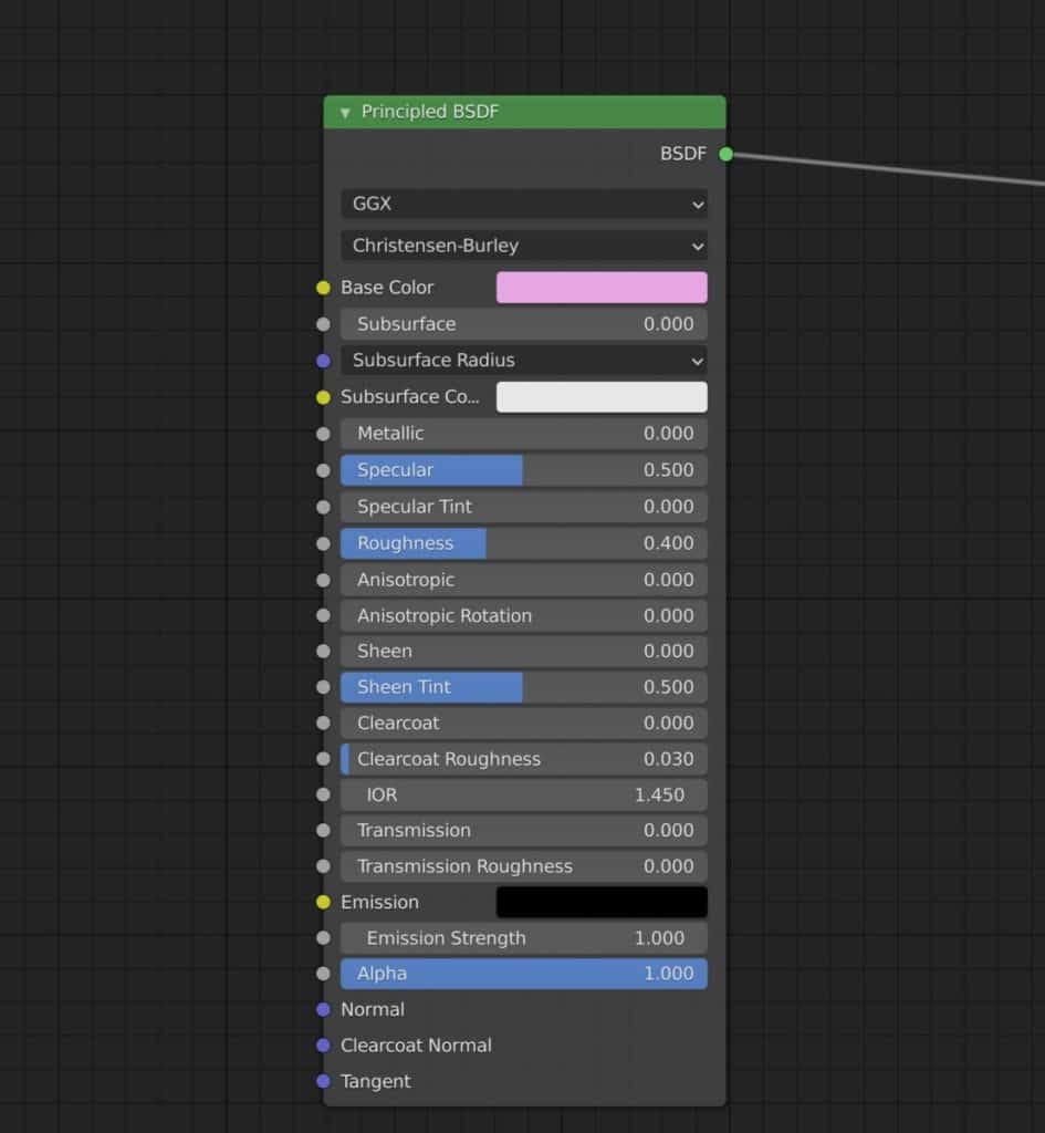
The Principled shader for example has a single output, labeled as BSDF. This term stands for bidirectional scattering distribution function, which in simple terms means the way light behaves when it makes contact with the surface.
This can be divided into three behaviors of light.
The first is reflection, where the light bounces off the surface and away from the object.
The second is refraction, where the light passes through the surface of the object and is redirected as it moves through the object.
The third is absorption, which is when the surface absorbs the light and does not allow it to escape.
Other outputs for shader nodes include emission, which is when a material creates its own light and acts as a light source. You also have volume outputs for defining how light affects the object’s volume rather than the material surface.
Color
These are simpler nodes that focus on one thing, creating color for the material. A shader node can generate a base color for the material by itself. But a color node can be much more versatile in how those colors are applied.
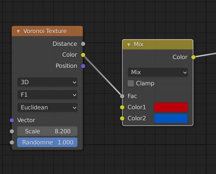
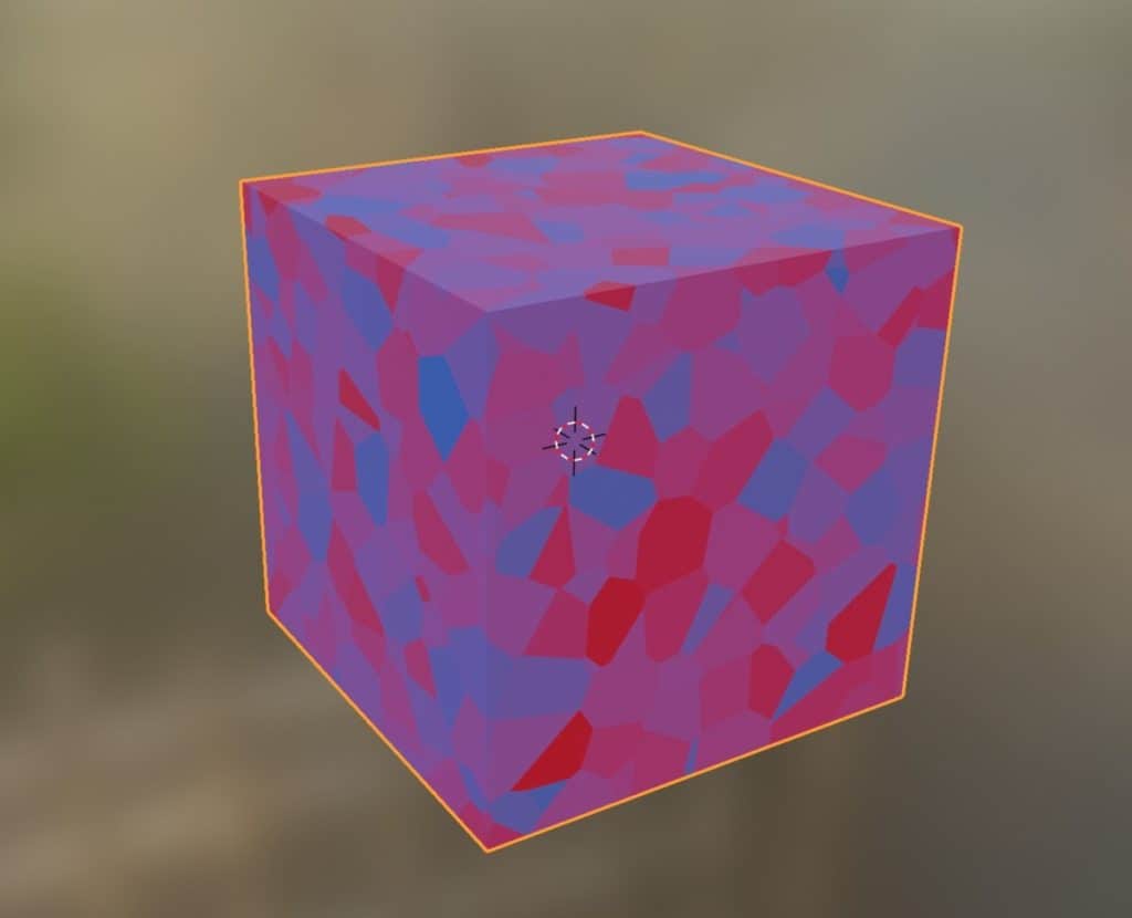
For example, you can have a texture node like a Voronoi texture that creates a pattern, but plugging it into the base color of the shader prevents you from changing the actual colors.
But you can correct this by adding a MixRGB node in between the texture and the shader. Connect the texture to the factor and then you can control the color by manipulating the values underneath.
Another example would be the hue/saturation node, which we can also apply to this Voronoi setup. By plugging the texture node into the color socket of the hue/saturation node, we can then control the hue, saturation, and brightness of the colors.
Converter
Converters are used to shift the data supplied from one form to another. These are perhaps the hardest type to learn because the use varies greatly from one node to the next, unlike texture nodes where it’s effectively doing the same thing but just in different ways.
These nodes can be referred to as support nodes that can be employed to control other node types. More advanced material artists will have many converters in their node trees to build really advanced materials.
Two of the most powerful nodes fall under this category. Math nodes are simple nodes that allow you to recalculate numerical values from the nodes. They are fantastic for creating custom shapes and textures even without the need for a texture node.
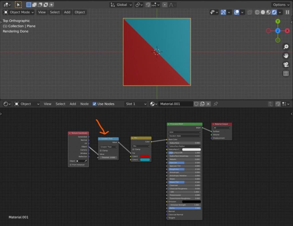
Below is an example of using the greater than function for the math node to create a simple diagonal line. The texture coordinate node is used to map the shape and the math node is used to calculate its effect. The color node defines the colors and the shader houses the light properties.
As converter nodes are generally used to either perform calculations or convert sets of data, you can use multiple of them in a row as pictured below.

We have taken out the color and shader nodes here so that you can see exactly how these nodes are working on the material. Of course, the texture coordinate node is still needed to map these functions to the object.
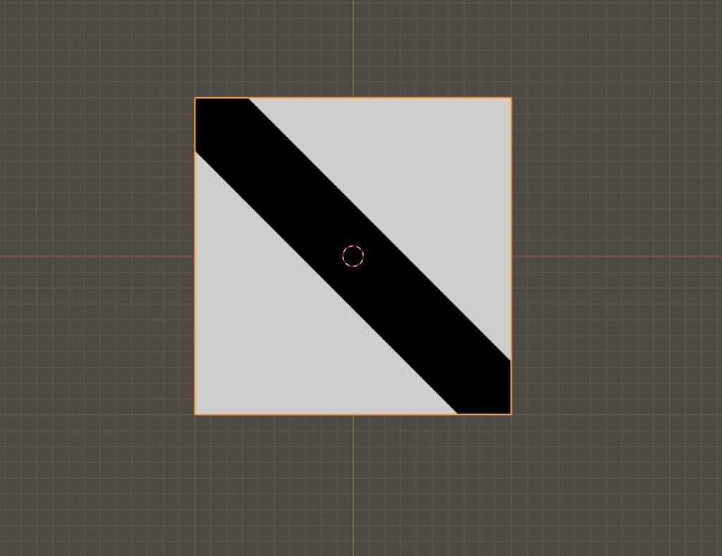
As you can see we now have a black and white diagonal line here for our texture. Of the three math nodes, the greater than node is used to create the cut-off point between the two colors, meaning there is no falloff between them.
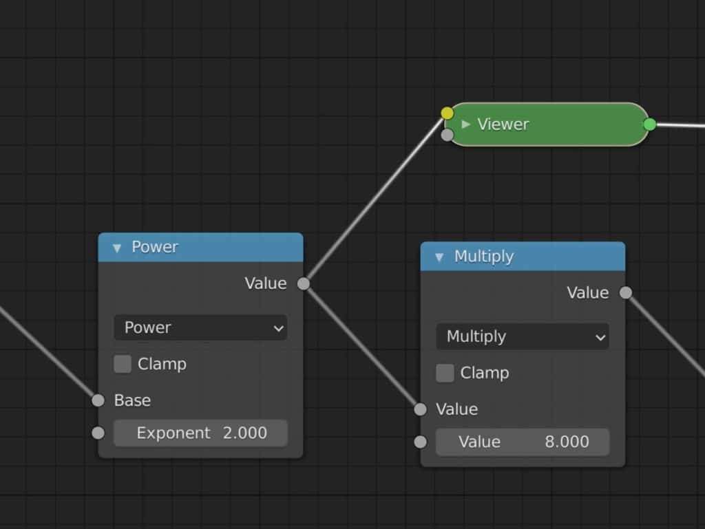
The power node creates the line itself but tells Blender that all values past a certain point, either positive or negative, will be white.
The multiply node is used in this setup to control how big the diagonal line is. The greater the multiple values is, the smaller the line becomes.
Of course, there are many other converters beyond simple math nodes, as you also have the color ramp on this list. The colormap is one of the most popular nodes of all as its versatility allows it to be used almost anywhere.
Texture
Texture nodes are exactly what they sound like! They allow you to create textures or patterns on your materials. These nodes are important because all materials will have a discernable pattern that allows the human eye to be able to tell exactly what the object is.
Wood is an easy example of a real wood material that requires a texture, as well as something like marble. But even materials that you don’t expect to have textures or patterns will. Glass is an example of a material that you might think does not need a texture, but it still has smudges, fingerprints, and scratches on the surface of the glass that are commonplace in the real world.
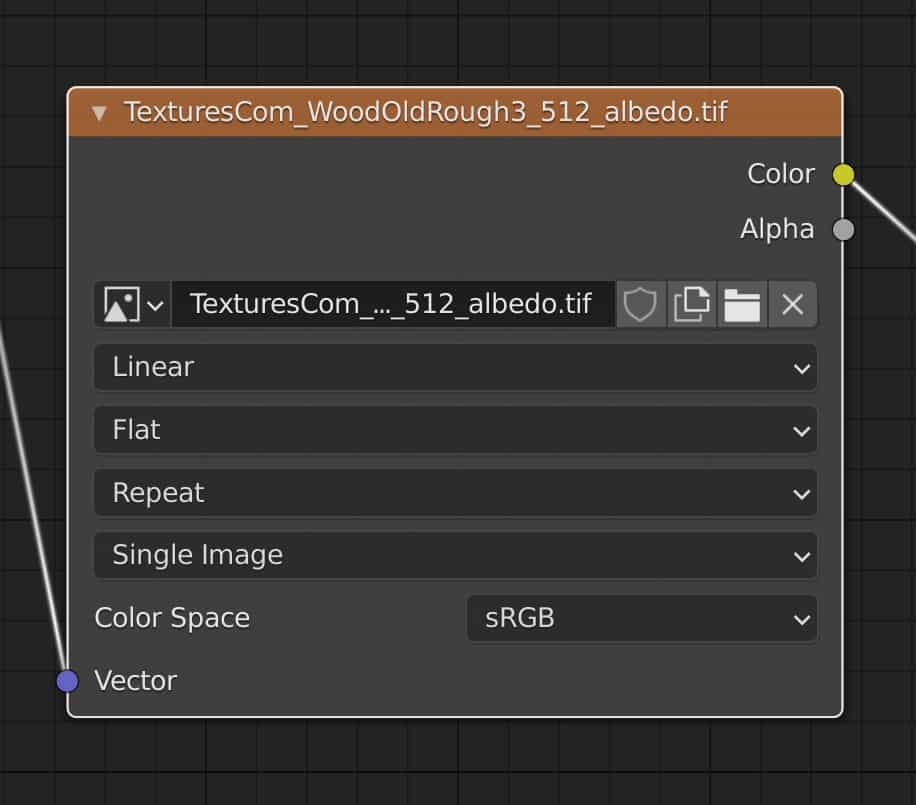
Image textures involve using external image maps to apply an existing texture to your material. It is common to use this method of material creation as it’s very time-effective.
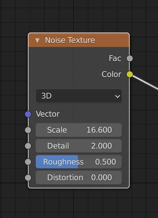
However many of the other texture nodes adopt a procedural approach. You have access to different texture nodes, like the noise texture, that calculates how a pattern will appear on the surface.
Unlike an image texture, these follow a procedural workflow, meaning you can change them in an infinite number of ways until your texture looks exactly the way you want.

A texture will normally be connected to the base color of a shader node, but can also be connected to other sockets as well. For example, you can connect it to the roughness input and used the map to control where the material is reflective and where it is not.
You also have the ability to add nodes in between to change the appearance of the texture. In the example for colors, we saw color nodes used to control the color of the patterns created by the texture nodes, which by themselves do not allow us to control color values.
Vector
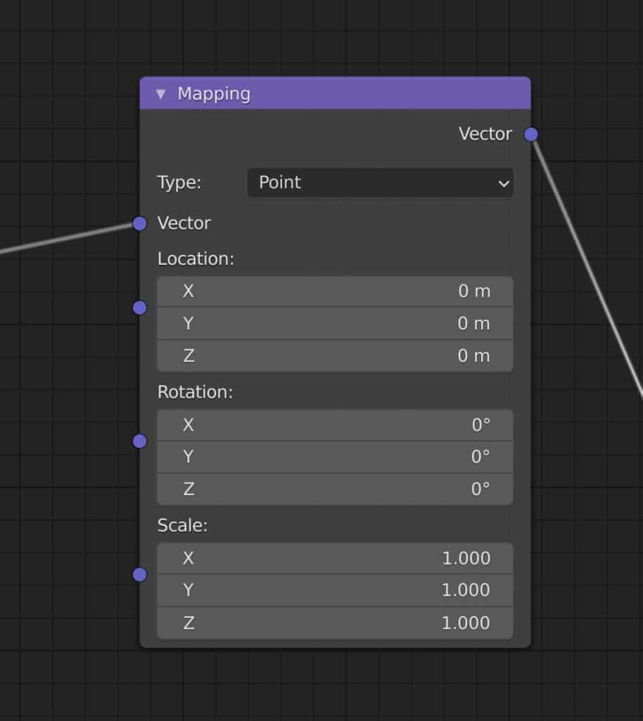
A vector is a form of data that is often attributed to coordinate systems and object transforms. They are effectively used as ways to control how materials are mapped out on an object. In our basic image texture example, the texture coordinate node is used to define the method used for adding the texture to the object, but the mapping node provides added control over the location, rotation and scale of that image texture. This is an example of a vector node.
Vectors are normally divided up into three channels. For the mapping node, these three channels are the X, Y, and Z axis. You can also consider color channels of Red, Green, and Blue as vector information.
As they are used as mapping data, vector nodes work alongside texture nodes for both mapping and displacement. The latter is a technique where the material data is used to shift the actual geometry of the model.
How To Organise My Node Setup?
There are several ways in which you can make your setups more manageable. The more nodes you add the more difficult it becomes to understand what is actually going on. Fortunately, there are a few visual methods to improve the organization of your node setups.
Assigning Colors To Nodes
One method is to assign colors to the node itself. Each type of node has a unique color to indicate which category that node belongs to, but what if you wanted to assign colors based on what stage they were at in the hierarchy? You can assign a color for each stage to make it easy to see which nodes are responsible for what tasks.
For example, in the setup below we have a procedural texture created using math nodes. The creation of this texture is divided up into three parts. The first is used to calculate the texture, the second is used to assign the color and the third to control the material properties. Each stage has been given a specific color to define it in the shader editor.
This immediately makes it clearer to the user or anyone who might view the setup that there are specific stages to the node tree for creating the material.
To assign a color to a node, press the N key on your keyboard to open up the side panel. Then with the node selected, tick the checkbox that is labeled as color. Then you can choose the color that you want to assign to each node.
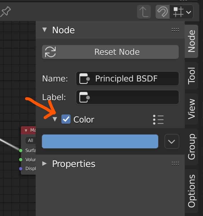
Make sure that the color you choose does not make it difficult to view the nodes’ settings. As the text is mainly white, darker colors are a better choice to use as the backdrop to your nodes.
Labeling Your Nodes
We have already covered this, but labeling your nodes can be another way of organizing your node tree. This works particularly well if you have more than one of the same node in your setup, which is common.
To label a node, you go to the side panel in the sheer edit and one of the first options will be the label. The text box next to it will appear blank. Type in the new label for that node in the shader editor.
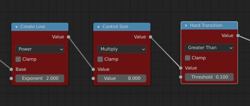
Below is an example where the labels for the math nodes have been changed to more accurately describe what the purpose of each node is for creating the texture.
The power node is used to create the line itself, so it has the ‘create line’ label. The multiply node is used to control the size of the line, so it is given the label of ‘control’. The greater than node creates a hard transition from one color to the next, so that is the label it is awarded.
Frames
Another way of visually organizing your nodes is to use frames. A frame is effectively a box to store a group of nodes inside. You can use this to divide up your node tree based on the different stages or node types used.
Adding a frame is similar to adding a node, you go to the add menu and then find the correct category, which in this case is the layout category. Then you can add and position your frame in your setup. You can position nodes inside of your frames by dragging and dropping those nodes inside.
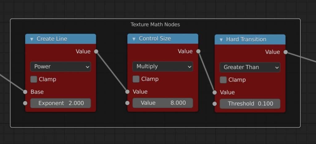
Then you can move the frame and it will move any nodes inside along with it. The frame may not have a label so you can add this the same way that you would label a node in the side panel. The same applies to adding color to a frame.
Making Life Easier With The Node Wrangler Addon
If you do not know what an add-on is then you are probably very new to Blender in general. An add-on is a script that can be enabled to improve an aspect of the Blender experience. There are many powerful add-ons available but perhaps the most famous of all is the node wrangler.
This add-on introduces a variety of new tools and hotkeys to make organizing your node trees far easier. For more recent versions of Blender, this is an add-on that is enabled as standard. But you may still want to double-check this as it is one of those add ons that you should always have switched on.
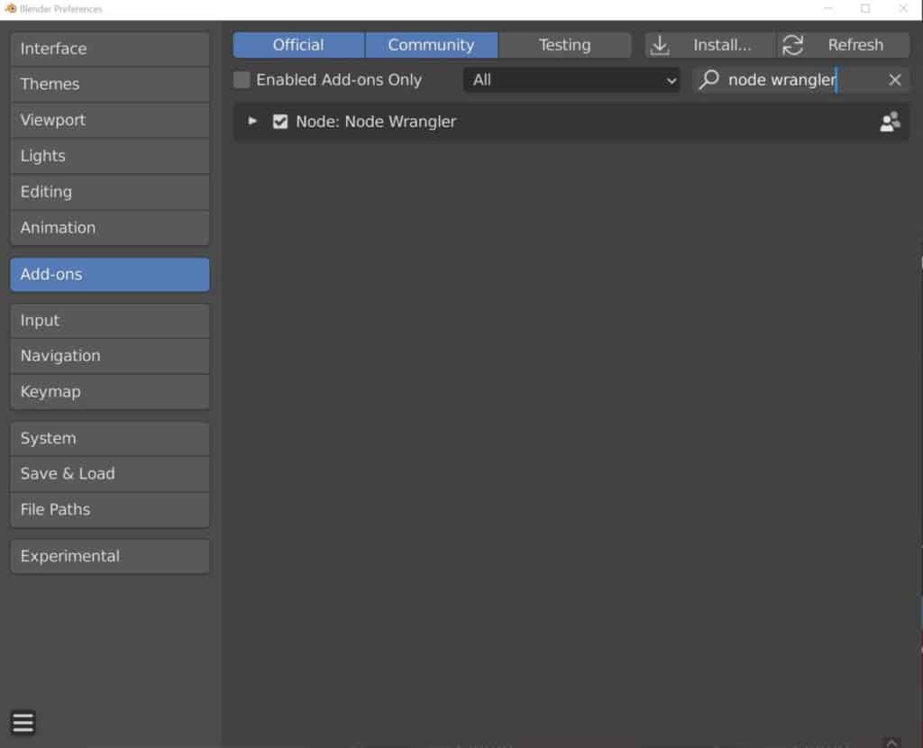
To enable an add-on in Blender go to Edit > Preferences > Addons and in the search bar at the top type in node wrangler. You will then see the add-on in the list below, and if it is not ticked, make sure to tick the box and exit the preferences panel.
What Can You Do With The Node Wrangler Add-On?
In all honesty, this could be a 7000-word post in itself, so below we have the top two features that you will use the add-on for and show exactly how to use them.
Adding A Full Texture Setup With A Single Hotkey
Perhaps the most notable feature of the add-on is the ability to set up a PBR material using a single hotkey. Select the principled bsdf shader and then using the hotkey combination Control + Shift + T. This will open up the file browser and allow you to locate an image texture that you want to use for your material.
Select all the texture maps that you want to use by holding down the control key. You can select Albedo, Normal, Height, Metallic, and Roughness maps of the same texture. You can find these maps in places like Poliigon and textures.com

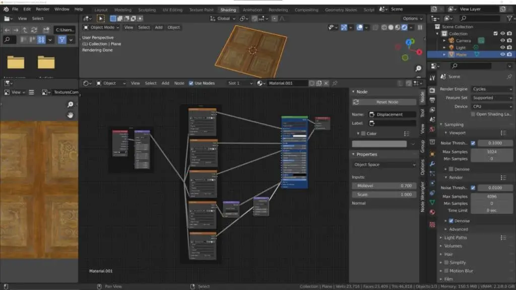
When you are ready to import your textures click on the blue Principled Texture Setup button at the bottom. What happens next is truly spectacular, as Blender then creates an entire node setup based on the maps that you selected. All the needed nodes are added and each texture is stored in its own node with the correct settings applied. You even get frames added to help with the organization.
The setup in the image below was automatically generated by selecting and importing the same texture maps listed in the image above, with no other button presses required.
The Viewer Node
Another really cool trick that you can use the node wrangler for is to view how individual nodes are affecting your material. If you use the hotkey of Control + Shift + LMB on a specific node, then Blender generates a viewer node that automatically connects to it, allowing you to view that node’s effect on the material.
Below is an example where we use the viewer node to preview the effect that the Power Node has on the material. The power node is plugged into the viewer and then the viewer goes straight to the material output.
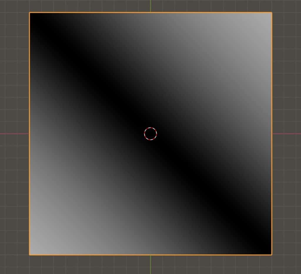
When we do this the texture changes in the 3D viewport based on what we have selected the viewer node to show. As you can see below we are able to view how the power node creates the black and white sections of the texture. We can then use the viewer node to select other parts of the chain so that we can see the whole process.
Are There Other Ways To Create Materials In Blender?
So if after all that you decide that creating materials exclusively using nodes is not for you, then what other ways are there to create materials in Blender. Well, you will always need to use nodes to a small extent, unless you stick to creating really basic materials from the properties panel.
But another method for texture creation is to paint your own texture using the image editor. This approach involves using a UV map of your model and then creating a base image that you will then paint on to create your own texture using Blender’s own suite of brush tools.
This is certainly a more artistic method of being able to create custom-made textures and takes a lot of practice to get good at, much like learning to use nodes. However compared to using texture and converter nodes to generate procedural textures, the art of texture painting is a completely different workflow.
Of course, you can also combine the two, using the painted texture and then expanding on it in the node editor.
Thanks For Reading The Article
We hope that you were able to get the information that you required from this article. Below we have a list of additional topics that we think you may be interested in…
- How To Paint Transparency Onto Your Image Texture?
- How To Change The Color Scheme Of The Blender Interface?
- How To Make Glass Transparent In Eevee?
- How To Apply An Image Texture To An Object?
- How To Make Your Background Transparent In Your Renders?
-
Animation Ready Hard Surfaces in Blender
Preparing hard surfaces for animation with optimized topology in Blender.
-
Symmetry for Hard Surfaces in Blender
Ensuring symmetrical perfection in hard surface models with Blender.
-
Detail with Shrinkwrap: Blender Modelling
Achieving intricate detailing with Blender’s Shrinkwrap modifier.