When working with geometry nodes, we also have the ability to work with the various attributes associated with our geometry that can be used to influence our node setups.
The normal attribute defines the direction of our face domain, allowing us to control other nodes such as the extrude mesh node to determine which of our faces are going to be extruded. The normal attribute can also be used in other scenarios as well to control the selection and direction of our influenced geometry.
In order to successfully use our normal attribute, we first need to be able to identify where the normal attribute is located in Blender, what type of data it is, and the various ways in which it can be used for our geometry node system.
What Is An Attribute In Geometry Nodes?
Before we can focus on the normal attribute itself, we need to answer the question of what an attribute is in geometry nodes.
An attribute refers to a specific type of data that is stored per element. This data can take on a variety of different forms or types, such as vector data or Boolean data. The element in which an attribute is stored can also be referred to as a domain and an example of a domain can include edge, face, or vertex data.
Different domains will have different attributes associated with them. Some of these attributes will be pre-built such as the normal attributes for faces and the position attributes for points or vertices.
In Blender, attributes are primarily used to control our node systems by defining what some of our parameters are calling. An example of this would be to use the position attribute to call the separate geometry node to select specific vertices to take apart from the main mesh.
The normal attribute node can also be used for scenarios like separating the geometry, deleting our geometry, or even extruding it.
All we need to do is know how to call that specific attribute to be used when a node requires it.
What Is The Purpose Of The Normal Attribute?
In traditional 3D modeling, normals represent the direction that our geometry is facing. Our vertices, edges, and faces all have an inward direction and an outward direction, and the outward direction is the normal direction.
In practice, an artist will always look to ensure that the outward-facing normals are visible to the scene camera and any inward-facing sides are invisible. Failure to do this can cause issues such as backface culling in video games where that geometry is not visible because the inside of the geometry is typically not rendered.
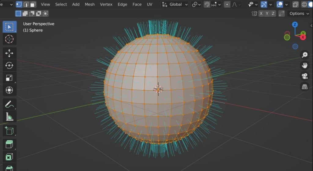
Below we have an example of a UV sphere where we have activated our viewport overlays menu to display normals pointing out of each face. The normal direction is defined by the blue lines in this example.
The normal attributes in geometry nodes follow similar principles and they can be used to define specific nodes that influence the geometry.
A common example of using the normal attributes in geometry nodes is to be able to call our normal attributes to define the selection of our exclusions.
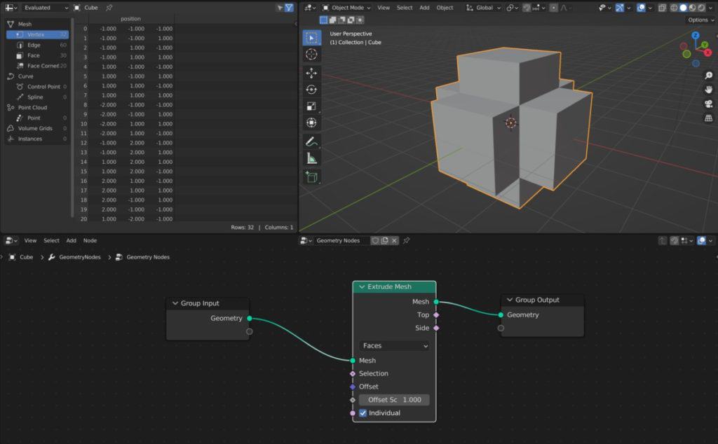
Let’s take a default cube as a basic example. The default cube has six sides for these sides, point outwards along either the X or Y axis, while the other two will point up or down on the axis. If we were to use the extrude mesh node by itself, then we would be able to extrude all six of our faces as seen below.
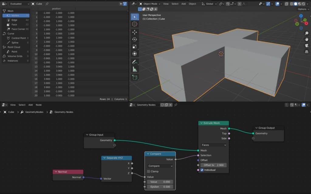
Let’s say we only wanted to extrude the faces that are pointing in the X&Y directions and are not pointing up and down on the axis. In other words, we want to extrude all of our side faces. If we take a look at the extrude mesh node we will see that we have a selection input that can be used to define which faces are extruded.
We’re going to use this to help cool our normal attributes so that we can use that attribute to define our selection. Bring up the add menu and then type in normal in the search bar. Select the normal node from this list as it should be the only one, and then position it in your node tree before connecting it to the selection input.
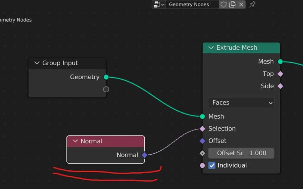
Simply connecting the normal node to the selection input changes nothing with regard to our model. The reason why is because we are simply telling our extrude mesh node to define our selection using the normal attribute, but we are not telling it how to define it.
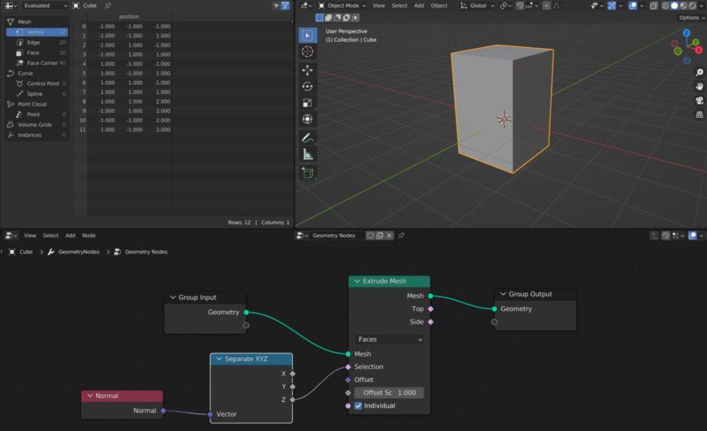
In our example, we want to not extrude the top and bottom faces. To do this, we are going to be using a separate XYZ node. Open up the add menu and then search separate XYZ node and connect it in between the normal node and the extrude mesh node. Then use the X output and connect it to the selection.
At this point, only the top face will begin extruding. This is because by default the top face is the only face on our cube to have a value greater than zero on the axis. We can confirm this if we take a look in the spreadsheet.
To truly define which of our faces we want to control, we need to use a math node or another utility’s node to act as that control point.
For our example, we want Blender to compare the value of each face on the axis. And if it falls within a certain range, we want Blender to use that face as a part of the extrusion. Our best choice for this is going to be a compare operation.
Add in a math node and then change the type of operation from add to compare using the math menu. Make sure to position the math node after the separate XYZ node. Then connect the Z value to the top value input and set the second value input to 0.
If we take a look at the 3D viewport now, then we will be able to see that the only faces being extruded and the side faces, and we can confirm this by manipulating the offset scale value of the extrude mesh node.
This is one example of being able to use the normal attributes to control other nodes that manipulate our geometry.
If you want to learn more about Blender you can check out our course on Skillshare by clicking the link here and get 1 month free to the entire Skillshare library.
Can I Flip Normals Using Geometry Nodes?
In traditional 3D modeling, we have the ability to flip our normals to ensure that the outward-facing direction is doing exactly that, facing outwards.
We are also able to do this using our geometry node system and we have a specific node that allows us to flip our faces. This is known as the flip faces node.
Below is an example of a cube where all of the faces are pointing in the wrong direction. The face orientation option has been enabled in the overlays menu to display the direction as a color.
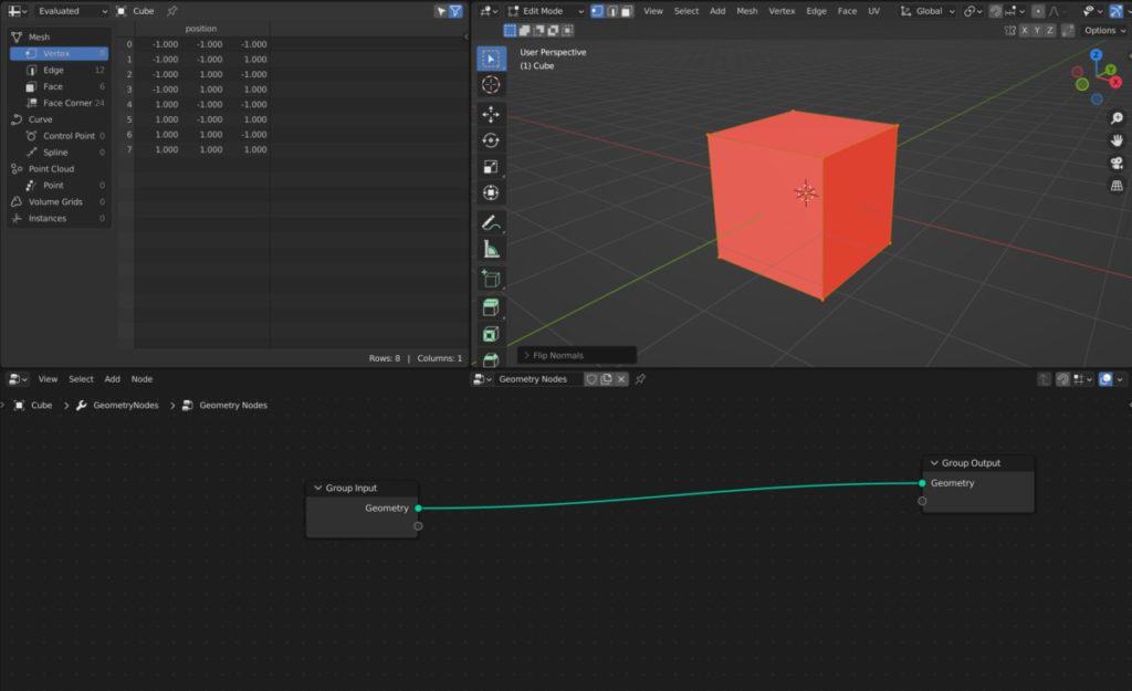
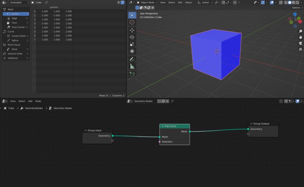
The Cube is currently red and it needs to be blue in order to be facing the correct orientation.
With an empty setup, it’s easy enough to use the flip faces node by itself to reverse the orientation of all of our faces. Simply add the flip faces node to your node tree. When it is set up it will correct the direction of the faces.
3D artists often spend hours a day working on their projects and that means a lot of time staring at a monitor, which can be harmful long term to our eyes. Recently we started using glasses that protect against glare and blue light for a more comfortable viewing experience allowing us to work longer on our projects.
You can check out the glasses that we use with the link here.
Thanks For Reading The Article
We appreciate you taking the time to read through the article and we hope that you have been able to locate the information that you were looking for. Below we have compiled a list of additional topics that are available for you to view and learn more about Blender.
-
Bevel & Chamfer: Blender’s Edge Mastery
Mastering the application of bevels and chamfers for sharp edges in Blender.
-
Non-Destructive Workflow in Blender
Embracing a non-destructive workflow for flexible modeling in Blender.
-
Detailing with Booleans: Blender Techniques
Incorporating Boolean operations for intricate detailing in Blender.