3D modeling does not always require you to add new geometry to your model continuously, and more geometry is not the same as more detail. Just as important as adding geometry with tools like extrude and inset is the ability to delete and dissolve unwanted geometry from your mesh.
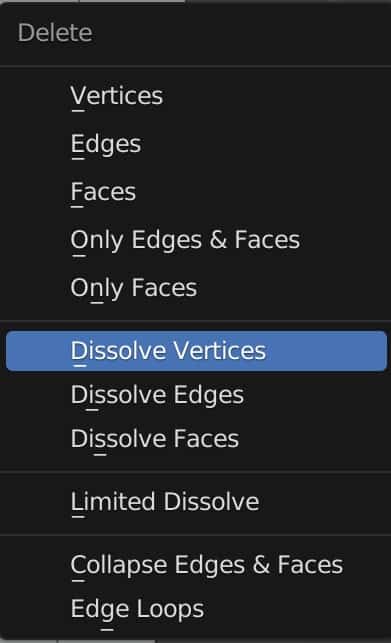
To delete geometry from your model, go to edit mode and select the geometry you wish to delete. Press the X key to open the delete menu, where you can delete or dissolve the various forms of geometry.
Many objects can only be created by deleting your geometry, while dissolving geometry is an excellent way of cleaning up your object’s topology.
How To Delete Geometry In Blender?
Deleting an entire object in Blender is easy, as all you need to do is select the object in either the viewport or the outliner panel, press the X key and then confirm to delete your selection.
The process of deleting geometry is essentially the same, but various options to choose from alter how the delete function works.
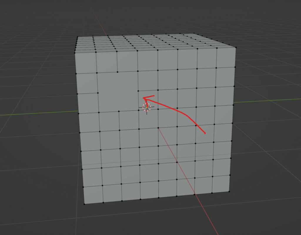
To delete your geometry, select an object and go into edit mode. The entire model will initially be selected.
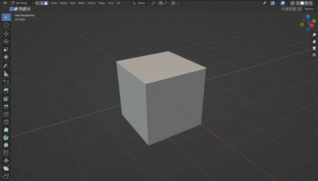
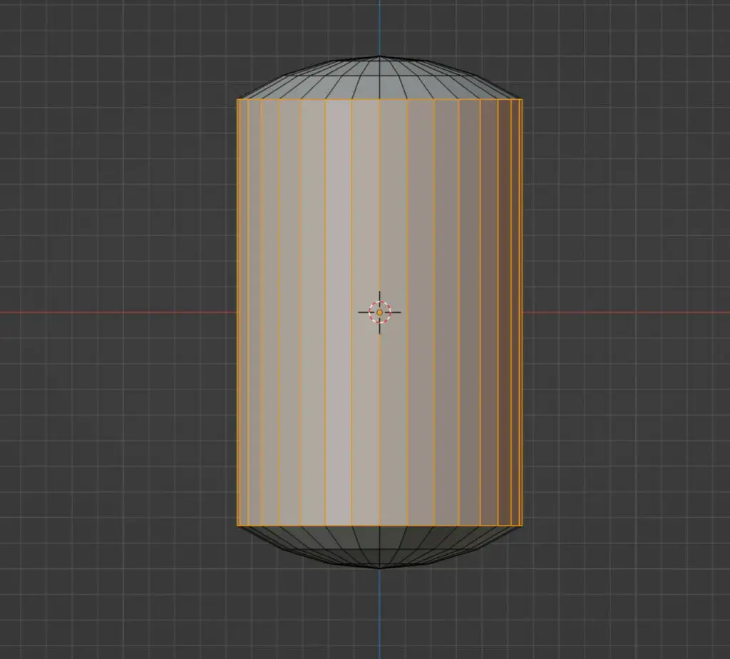
Use either vertex, edge, or face select and then select the geometry you wish to delete. For example, we can select the top face of a cube.
The same hotkey that allowed us to delete our objects in object mode will also allow us to delete our geometry in edit mode. Press either the X or delete keys to open the delete menu.
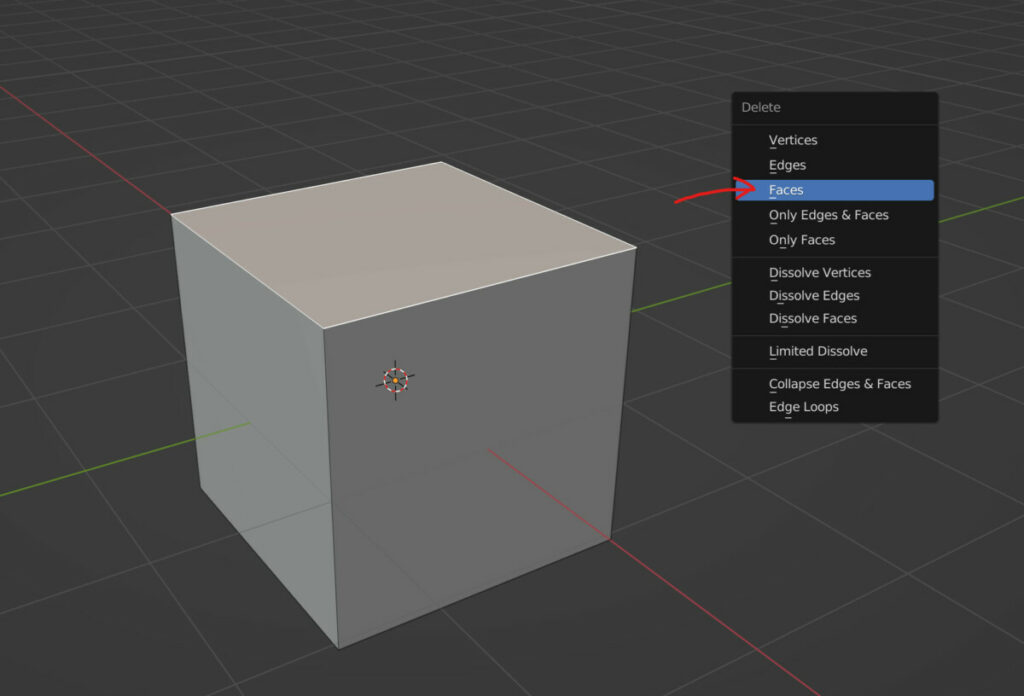
From here, choose the option most appropriate to you. In our example, we want to delete the top face, so we choose the top faces option from the menu.
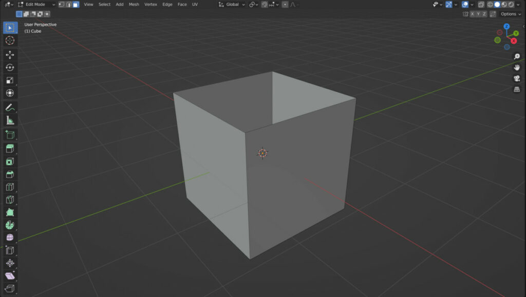
The selection is now deleted, and what was initially a cube is now an open-top box. For example, we can use different editing tools like the solidify modifier to add some thickness.
What Happens If We Delete All Of Our Geometry?
When you switch to edit mode on an object for the first time, all of that object’s geometry is selected. This means that it is immediately possible to delete your geometry.
You can grab, rotate, or scale an object in edit mode and these transforms will appear to operate in the same way as they would in object mode. However, there are subtle differences when using the tool in each mode.
The same principle applies to deleting object geometry. If we open the delete menu and delete all of the vertices, it will appear as though we have deleted the entire 3D option.
However, if you were to take a closer look, you would see that the object origin is still in place, and the object still exists in the outliner panel.
Of course, without geometry, you can’t do anything with the object, and it won’t appear in renders. You could still use an object without geometry, like an empty. For example, parent other mesh objects to the model.
Quick Tip: If you have no geometry, you can add a mesh primitive like a plane to introduce new geometry to the model.
How Deleting Geometry Works?
The simplest way to use the delete tool is to delete your geometry, but the type of geometry you choose will change what gets deleted.
Take the cube example; select the top face again and bring up the delete menu. The first three options in this menu are for the vertices, edges, and faces.
Deleting the face gives us the ideal result, as only the selected face is deleted and nothing else. But what about if you choose a different option?
If you choose to delete edges, the top face would again be deleted, along with all the edges used to create it.
However, you will also notice that the surrounding faces of the cube have also been deleted. This is because the removed edges were also integral to the structure of the side faces. Since they were removed, the side faces could not exist.
The vertices that construct the face are still maintained as they are not dependent on the edges, so they are preserved on the model.
On the other hand, deleting the vertices will delete all geometry dependent on that selection, including attached edges and faces.
So when we delete the vertices, all of the faces on the top and side of the cube are deleted, leaving us only a plane at the bottom.
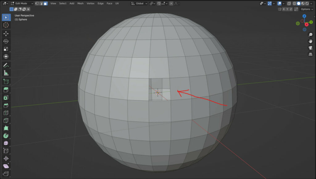
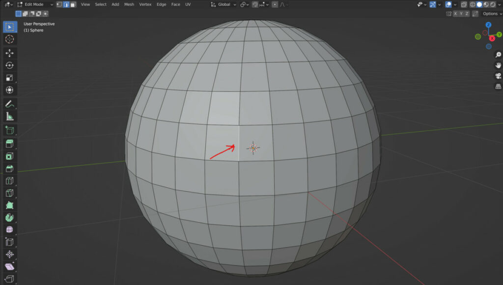
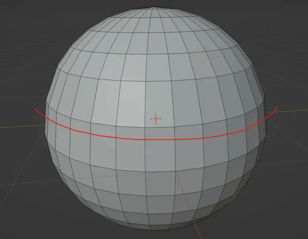
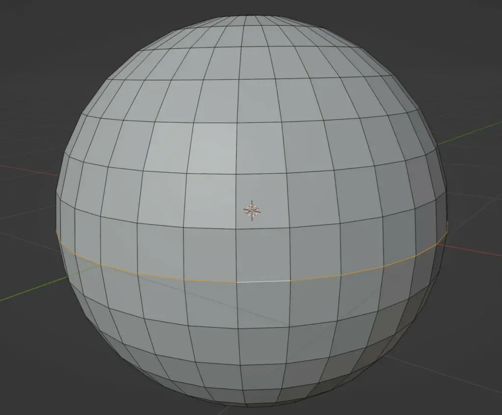
This behavior is the same regardless of the shape of the object. If we take a UV sphere as an example…
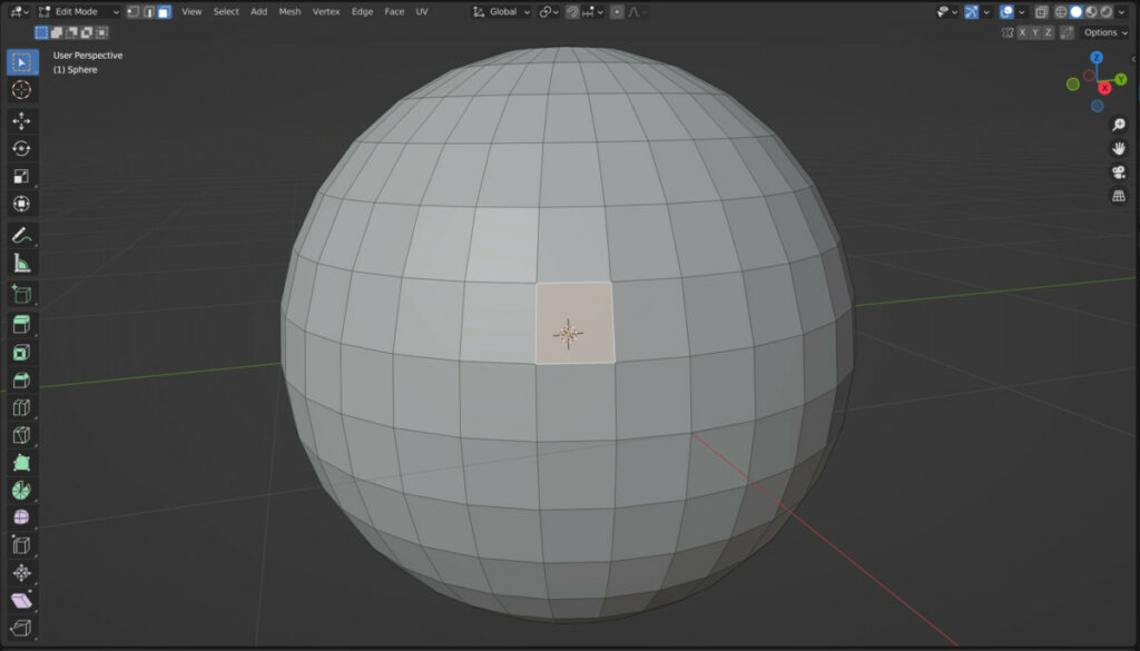
Selecting and deleting a single face using face delete will remove that one face but will not delete any other part of the model.
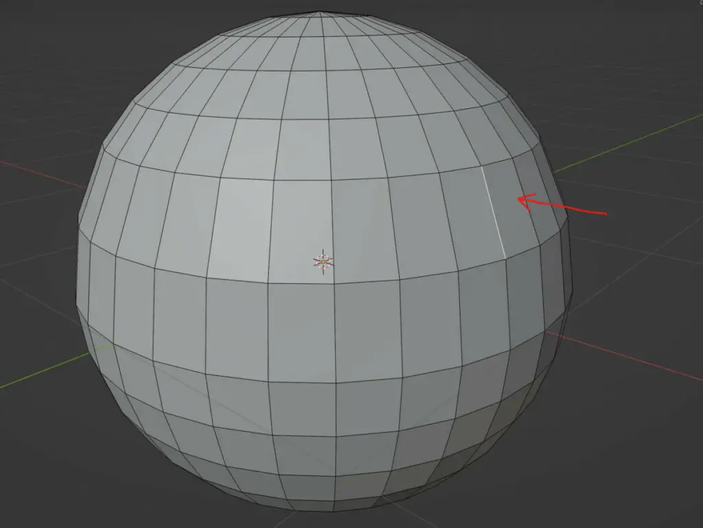
Selecting and deleting a single edge will remove the faces on either side of the edge.
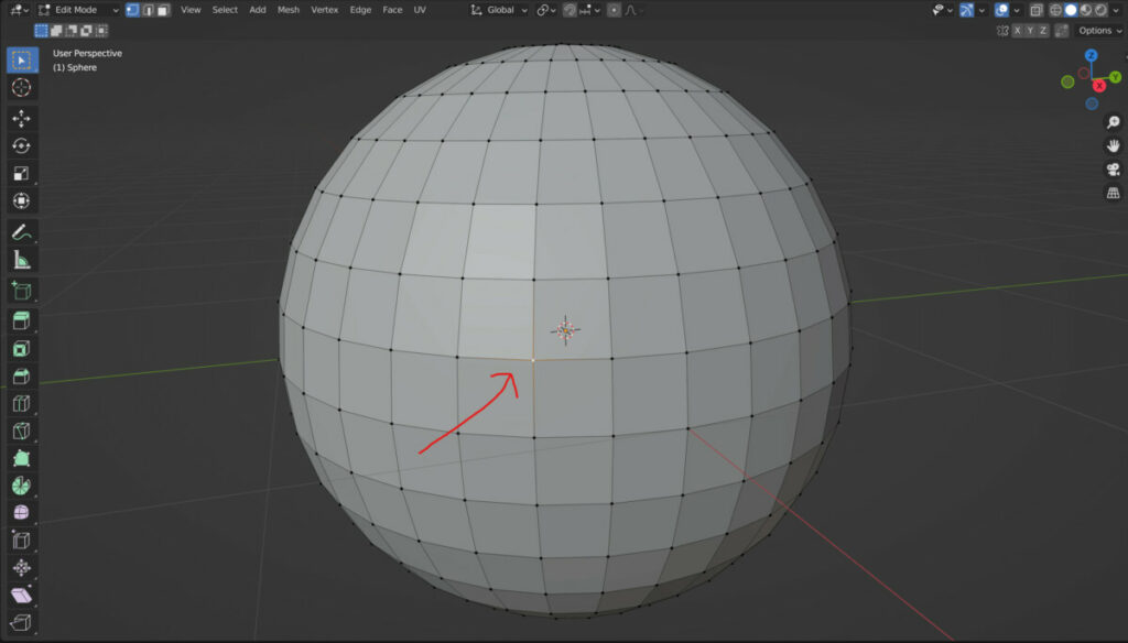
Selecting and deleting a vertex will remove all faces and edges that surround that vertex.
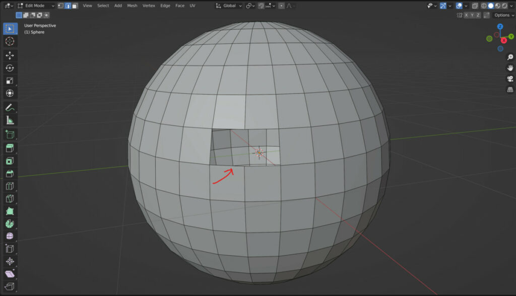
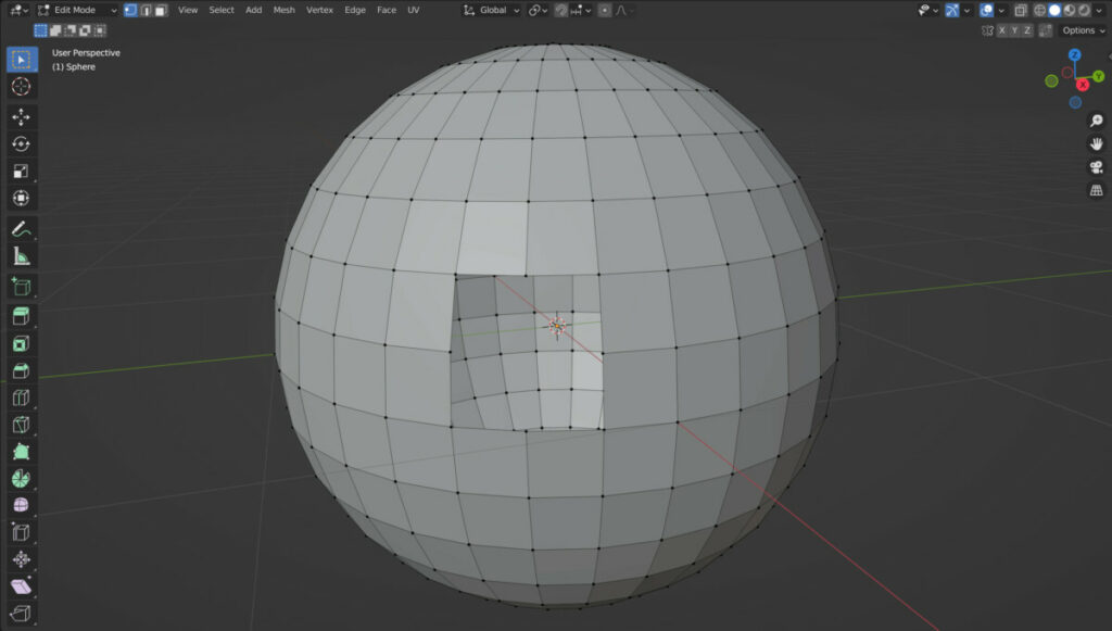
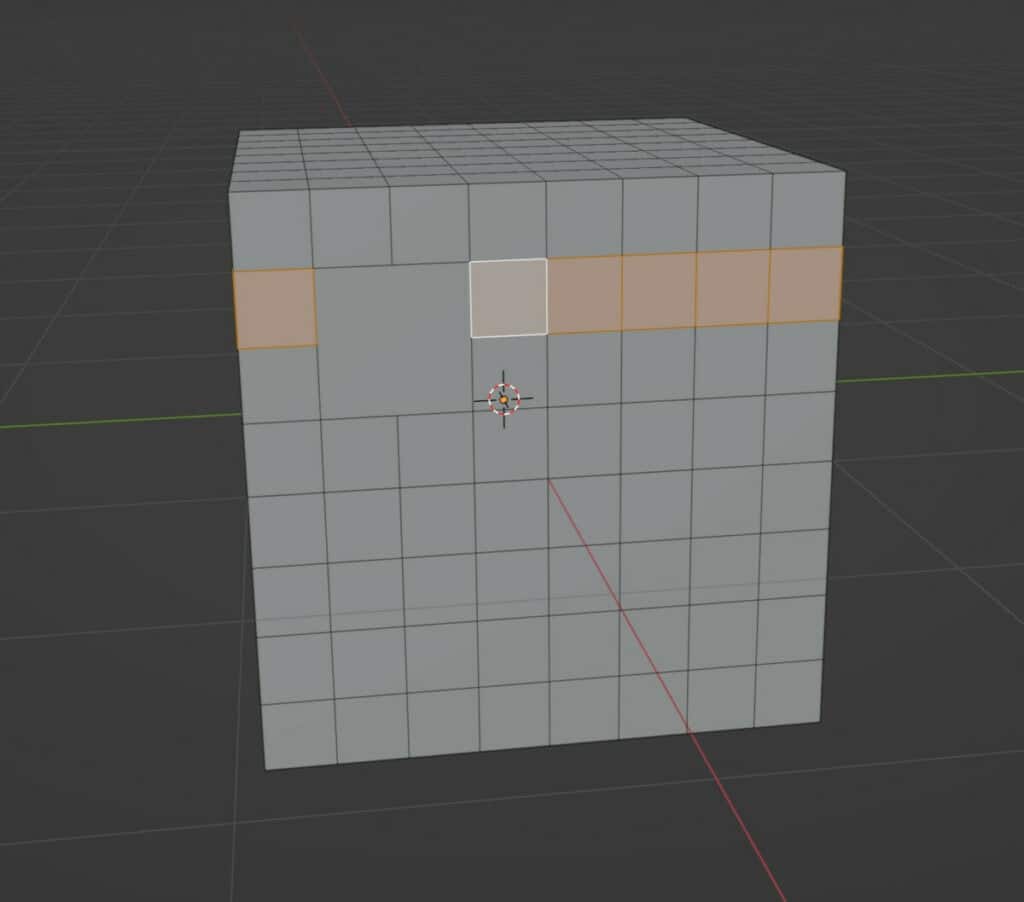
If you return to the delete menu, we will notice that we have two additional options for deleting geometry. These options are to only delete edges and faces, and to delete only faces.
If we select two faces that are side by side, and then choose the delete faces options, then the faces will be deleted as well as the edge that they shared.
However, if we choose the only faces option, the faces will be deleted but the edge between those faces will remain.
This is a similar case with the delete only edges and faces option. If we select multiple faces on our object and then choose to delete only edges and faces, then the edges and faces that were a part of the selection will be deleted, but any vertices will be maintained even if they are not connected to anything else.
How Dissolving Geometry Works And How It Differs From Deleting?
Not all situations require you to the Leech or geometry, and it can be a much better solution to dissolve geometry instead.
The critical difference between deleting and resolving is that deleting a specific geometry form, such as a vertex, will eliminate all surrounding geometry.
Dissolving, on the other hand, allows us to select and delete our geometry, but it will attempt to merge the surrounding geometry, changing the topology.
These options can be found in the second third of the delete menu, and we can dissolve vertices, edges, and faces.
The idea of dissolving is to maintain the model’s surface by merging any surrounding faces together if a vertex or edge has been dissolved.
Dissolving Vertices
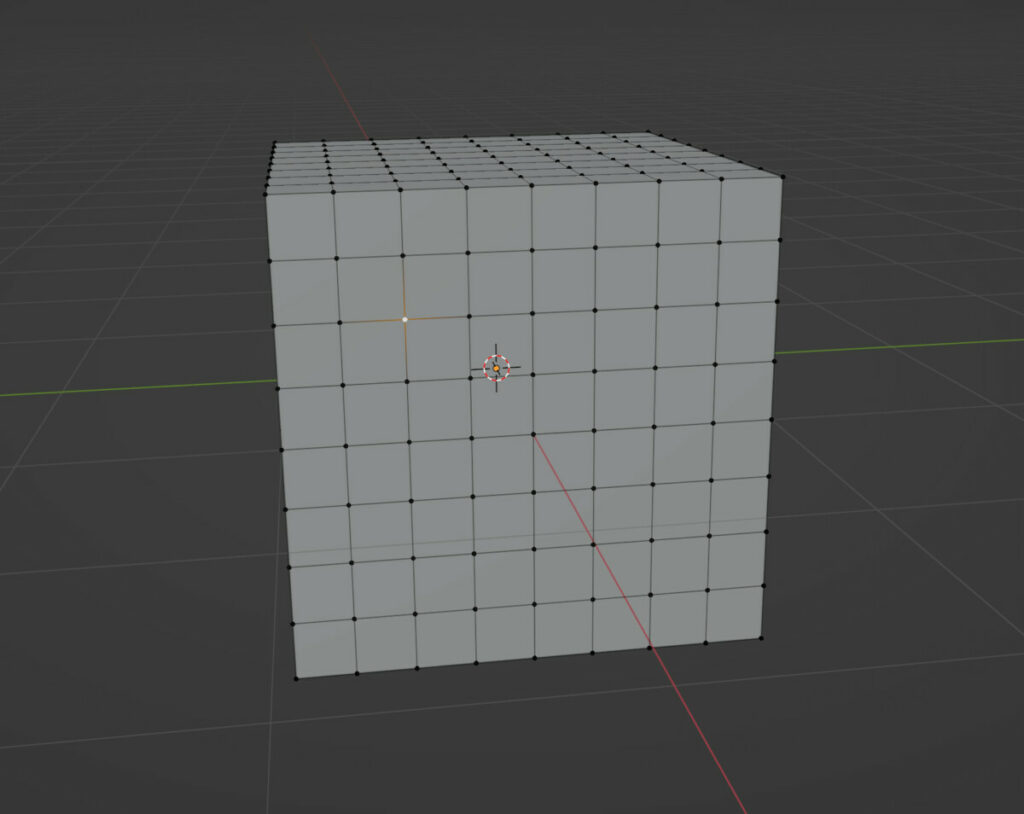
This time we will use a subdivided cube as our example and start by selecting a single vertex. If we delete this vertex using the delete vertices option, all of the surrounding edges and faces will be deleted. This creates a hole in our cube.
However, if we chose the dissolve vertices option, we would remove that vertex and the edges connected to it because those edges cannot exist.
However, the faces surrounding that vertex can be merged to form a single face.
This face has more than four sides and is technically classed as an end gone, which changes the geometry flow on our keep.
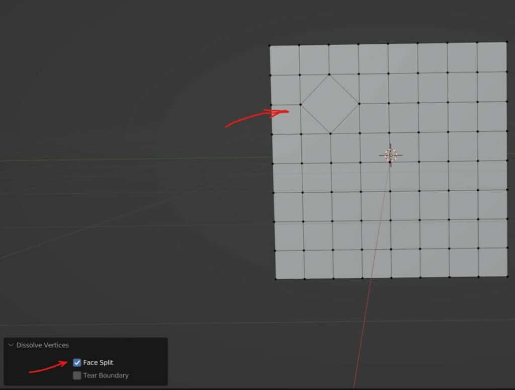
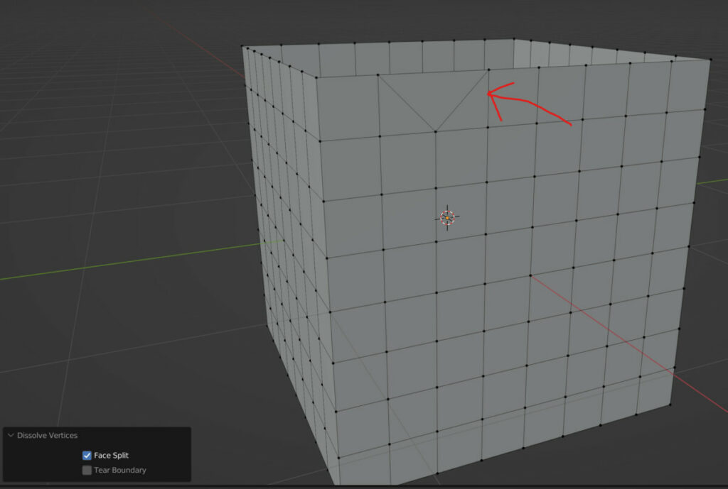
When you use the dissolve vertices tool, you will notice that we have a couple of options in the operator panel for this tool.
The first of these is the face split option. This will attempt to maintain the geometry at the face corners when ticked.
In our example, taking this box creates a diamond shape connecting all of the face corners from the previously connected edges to our dissolved vertex.
The tear boundary option is used to delete geometry found on the boundary of the surface rather than merge it.
Because there is no end boundary on our cube (The edges of the cube are not boundaries here gue to continued loops) we need to alter the example a little to demonstrate.
The entire top side of the cube is deleted, creating an end boundary at the top. Now we select a single vertex on the top row and dissolve the vertex.
Tick the tear boundary option in the operator panel, which will split at the face corners like the face split option.
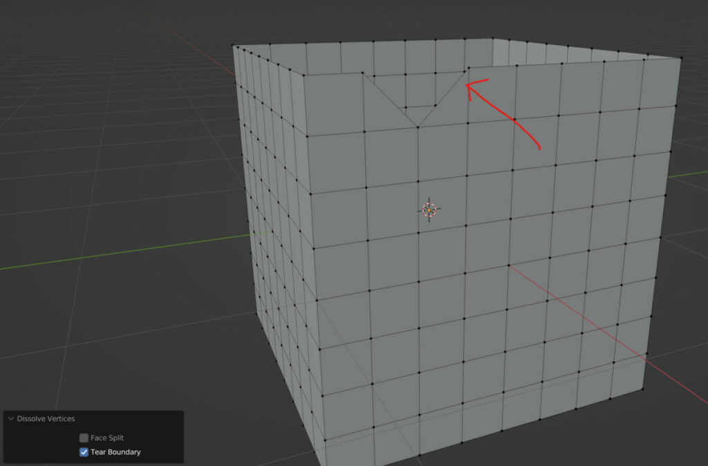
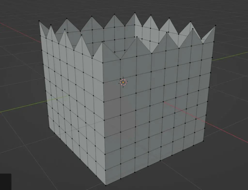
The main difference is that the middle face, where the vertex was positioned, has been deleted. Combined with a tool like checker deselect, we can dissolve geometry to create new patterns like the spike pattern seen below.
Dissolving Edges
Dissolving edges is the same process but with a different form of geometry. Select an edge and dissolve it to merge the faces on either side to form an ngon.
In the operator panel, we can use the face split option again to alter the topology flow. We also have the dissolve vertices option that dissolves the vertex shared by the edges.
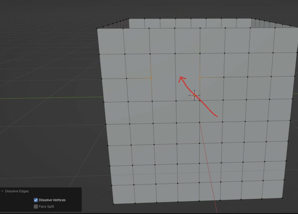
This option is best viewed when two edges are selected and then we transition into vertex select mode to view the vertices. Ticking the Dissolve Vertex option removes that middle vertex creating a single edge on either face.
Dissolving Faces
The third form of geometry that we can dissolve is the faces. Note that as dissolving reforms our topology, the order of dependence applies to that geometry. Because vertices construct edges, removing vertices can remove edges.
A single face cannot be merged into anything else, so selecting a face and then using the dissolve face option will not make any changes.
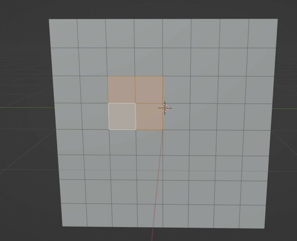
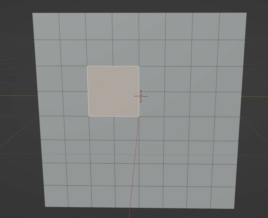
Selecting multiple faces simultaneously will allow us to dissolve that selection into a single one. In the operator panel we have a single option: Dissolve Vertices.
For this to work, we need our selection to form a more distinct pattern like an L shape, so instead of selecting four faces, we select three in the shape of an L.
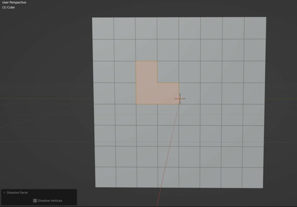
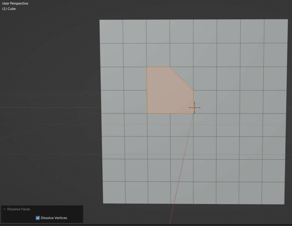
Enabling Dissolve Vertices will encourage Blender to connect the geometry at specific points.
Limited Dissolve
There are a view more options that allow us to dissolve our geometry based on other parameters aside from the type of geometry that we are trying to delete.
The limited dissolve feature allows us to reduce our geometry density using edge angles as the primary parameter.
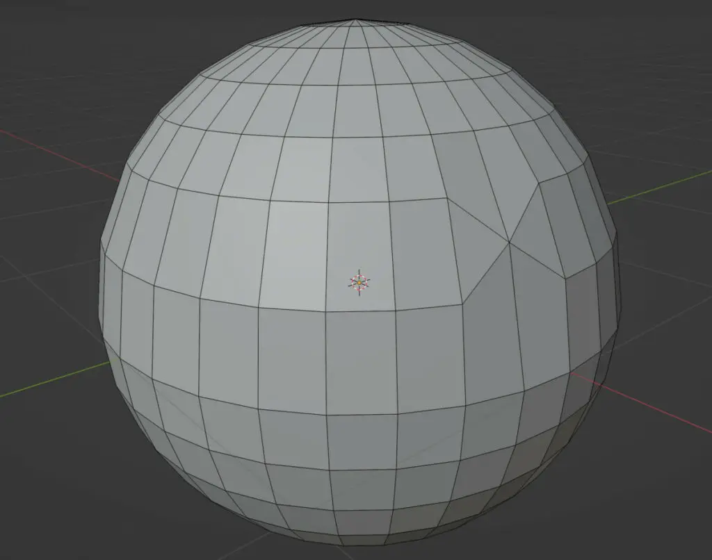
If we use limited dissolve on a subdivided cube, it will effectively reverse the effect of the subdivision. All edges and vertices that fall into the assigned threshold and have minimal impact on the objects shape are dissolved.
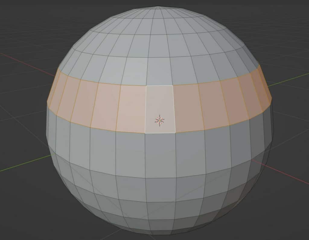
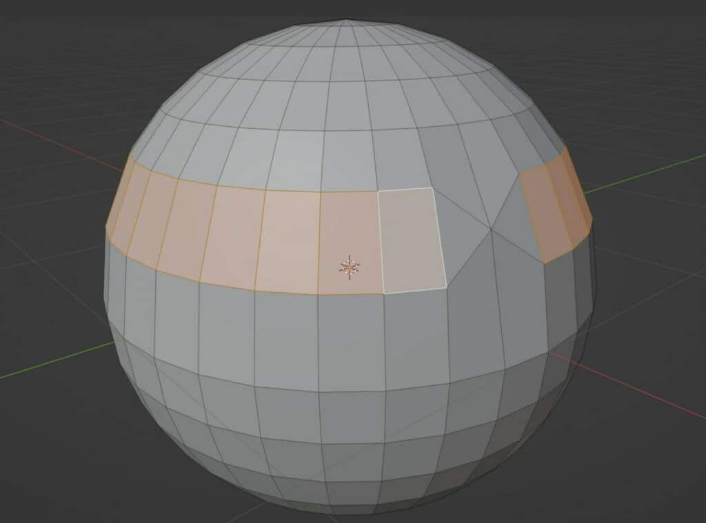
A better example of how effective the limited dissolve tool is would be with a UV sphere, where the angle continues to change as we move closer toward the poles.
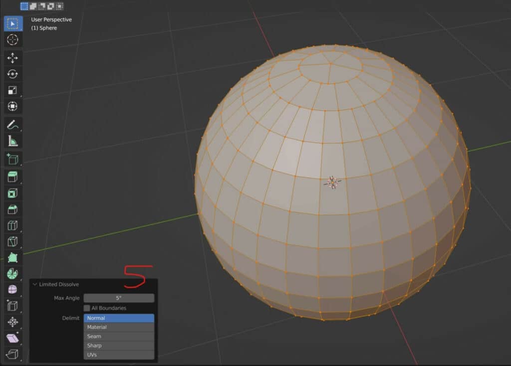
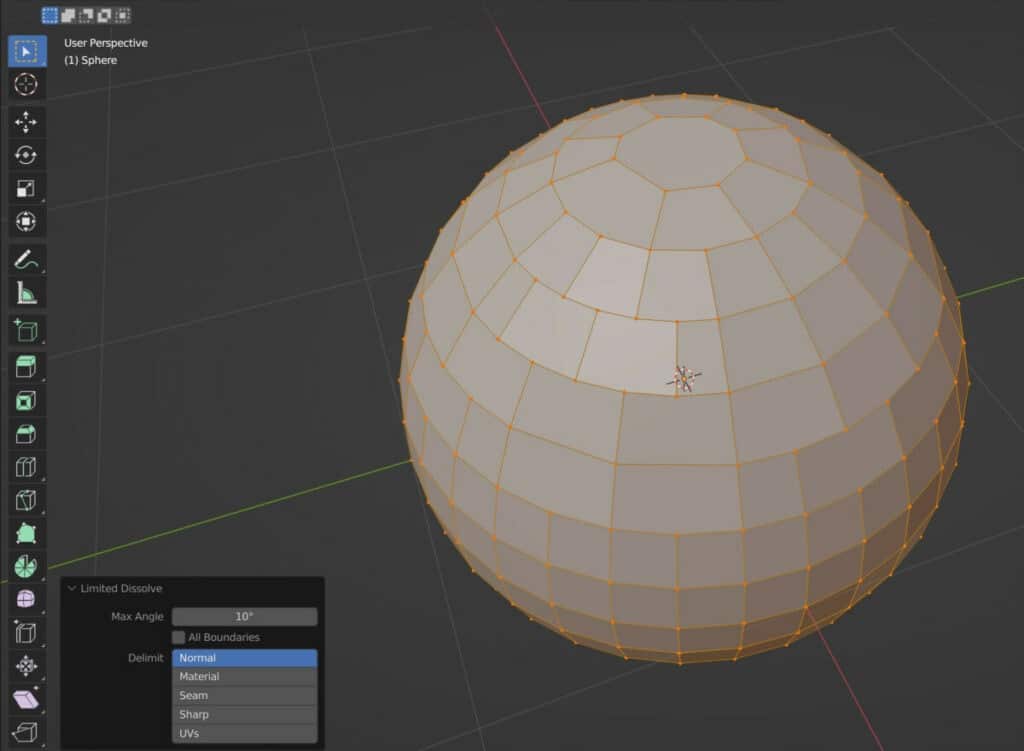
When using a max angle value of 5 degrees, the top of the sphere begins to merge its vertices. The more we increase the max angle, the further down the sphere the geometry dissolves.
In addition to the max angle, we also have the delimit options, which determine the secondary factor for how the geometry is dissolved and where.
For example, we can create a seam on our sphere, and by using the seam as the delimit, our limited dissolve tool will try to maintain the seam as much as possible.
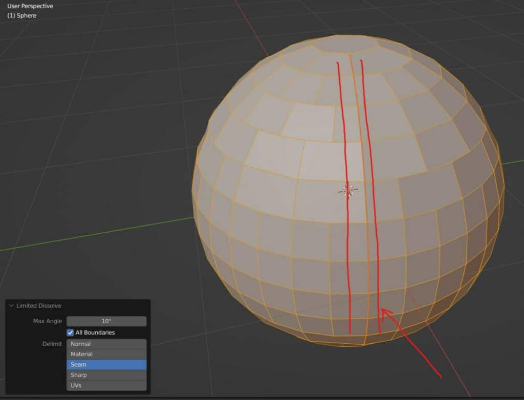
Reduce your geometry too much with the max angle and even the seam will eventually start to dissipate.
The following are a list of the different delimit methods and how they work…
- Normal: Based on the normal direction of the geometry
- Material: Attempts to maintain positioning of faces with a secondary material
- Seam: Edges marked as seams are prioritized
- Sharp: Edges marked as sharp are prioritized
- UVs: The objects UV map is used to define the limited dissolve based on the UV islands
Collapsing Geometry Like Edge Loops
The final two options in the delete menu revolve around collapsing and merging our geometry. The first of these is to collapse edges and faces.
This is best used when we want to collapse an edge ring to reduce our geometry. To select an edge ring use the hotkey Control + Alt + Left Click.
With edge rings the edges are not directly connected to each other but still form a consistent loop depending on the topology.
Collapsing an edge ring results in the merging of the edge loops directly above and below, dissolving the connected faces in the process.
Go to the delete menu and select the collapse edges and faces option to dissolve the edge ring and merge the geometry.
Another use case for the collapse edge/face tool is with topology. This acts as a great way of controlling your topology by introducing triangles.
Below we have an example of a single selected edge. The collapse tool will merge the vertices of that edge, changing the topology in the process.
To better demonstrate how edge flow is affected, let’s also view how our face loops are selected below and after.
The final option in the delete menu is to collapse the edge loops themselves, which reduces the amount of geometry but maintains the edge flow.
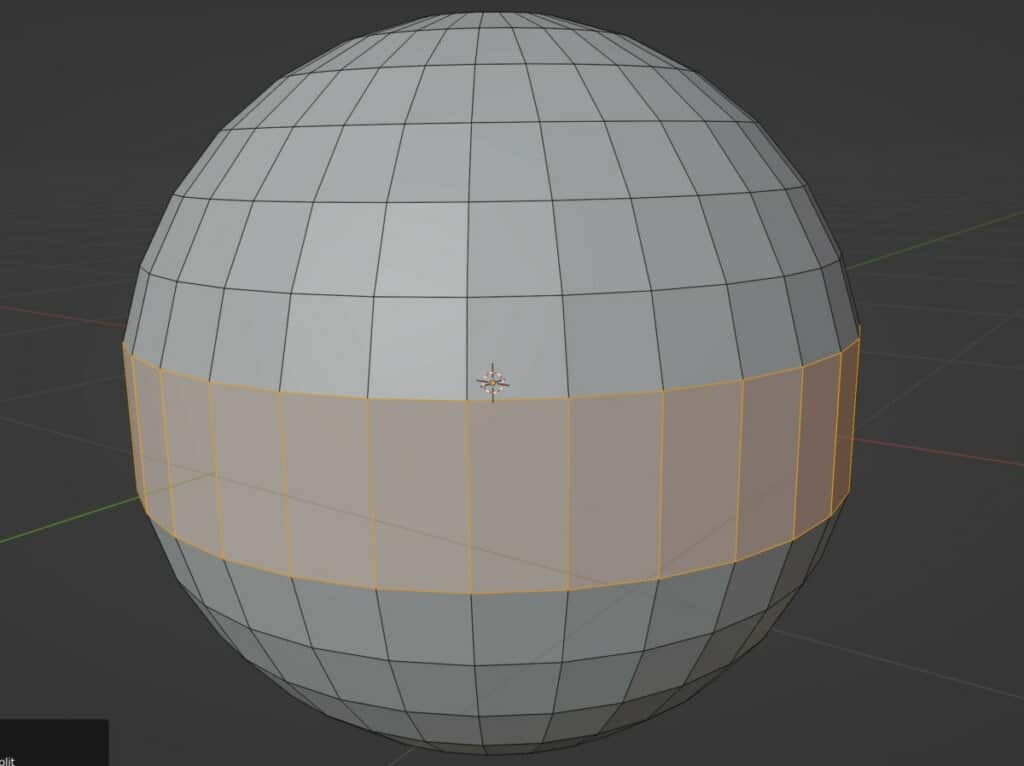
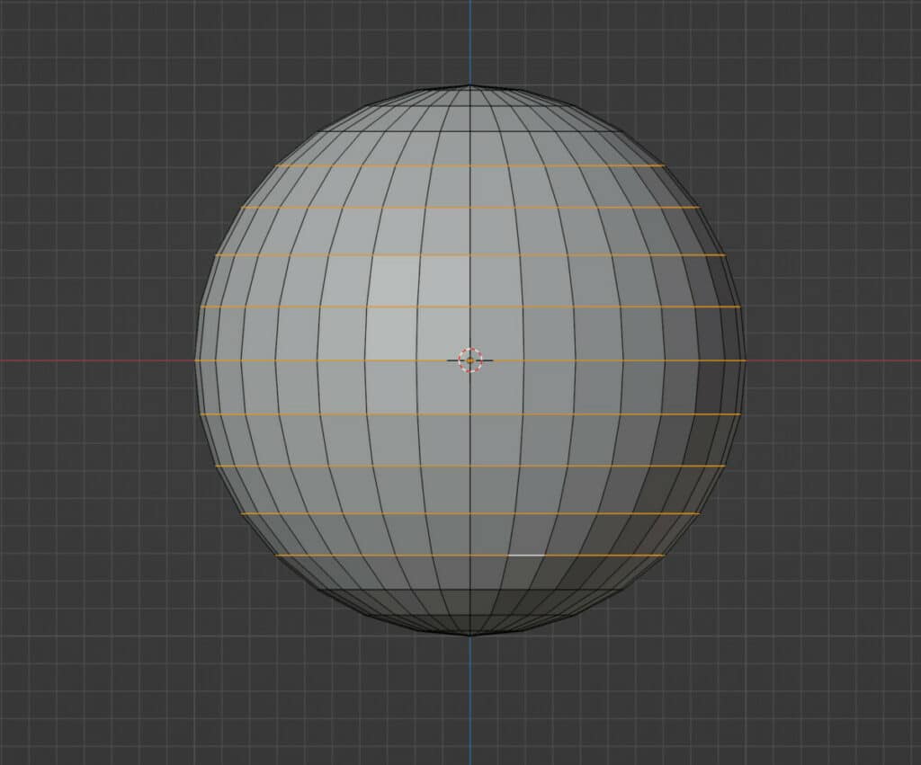
Note that you can select multiple edge loops simultaneously using the shift and alt keys to decrease your geometry further.
In the following example, we select multiple edge loops and dissolve them to create a new shape from our sphere.
Thanks For Reading
We appreciate you taking the time to read through the article. We hope you found the information you were looking for. If you are interested in learning more about the Blender software, you can check out a few of the articles we have listed below.
- Why Materials Get Deleted When You Close Your Projects
- Using The Add Tool To Generate Objects Quickly
- What Is The Shortcut To Adding A New Mesh Object
- How To Change Your Units Of Measurement In Blender
- Removing All The Grid Lines From The Viewport