Geometry nodes are the latest phase of Blender’s incredible development, and it introduces procedural 3D modeling using a node system. For this note system to be successful, it needs to imitate many of the tools we traditionally used in our viewports.
Perhaps the most common of these tools is the transform values of our model, in other words, changing the location, rotation, and scale.
To add the transport nodes, use the hotkey Shift + A to open the add menu. Go to where it says geometry, and then from the second menu, select transform and position it into your node setup. With this node, you can manipulate your geometry’s location, rotation, and scale on each axis.
The transfer node is one of the most straightforward nodes in the node system. But there are still a few factors about this node that are important to learn when it comes to how it manipulates the behavior of your model.
Adding Our Transform Node
The transform node will likely be one of the very first nodes that you have to learn. We procedural modeling just as it is one of the earliest toolsets to learn in traditional 3D modeling.
Click on the new button to start a new node tree with your selected model. You will have access to a group input node, which provides the information from the base model, and a group output node which transmits the new information to the object, changing its shape.
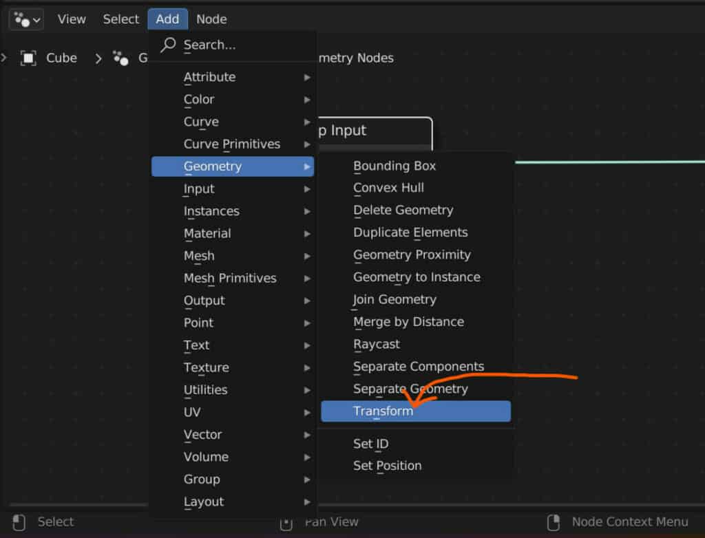
To add a transform node between these, open up the add menu by either locating it in the header of the node editor or by using the hotkey Shift + A. Next, you can either type in ‘transform’ in the search menu that you can find at the top of the ad menu. Or you can go to the geometry section, highlight it and then select transform from the second menu.
When you add a note, it will be glued to your cursor until you use the left mouse button to position it in your node tree. Hover it over the connexion between the group input and group output nodes until that connexion appears white, then the left click, and the transfer node will attach to the setup.
The Structure Of The Transform Node
If you have used the traditional modeling tools in Blender, then what you will see in the transform node will be no surprise. The first input of the transform node is for geometry, so in our example, we have the geometry from the group input used as the base for our calculations in the transform node.
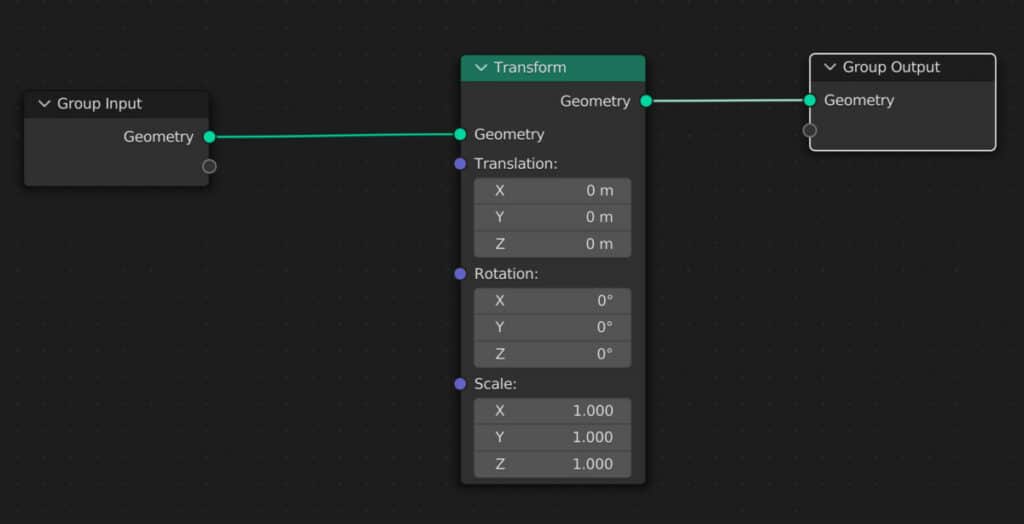
Below that, we can change the location, rotation, and scale of our objects’ geometry; the geometry input appears as a green circle. This color indicates that we are using geometric data.
However, our other three parameters, the location, rotation, and scale, use purple dots. This indicates that we are using vector data for these parameters.
Each parameter can be changed independently, as can each axis of that parameter. You can click and drag it to alter these values, or you can click and then type in a specific value. These parameters work almost the same way as they would in the side panel of the 3D viewports. So your scale, for example, would be set to one on each axis to represent the original size of the model.
On the output side of the node, we only have a single option: the geometry output. The structure, therefore, is that we take in the data from the group input node, which is the base model.
We then change that model’s location, rotation, and scale using the transform node parameters, and we send those changes over to our group output node using the geometry output.
The Effect On The Object Origin
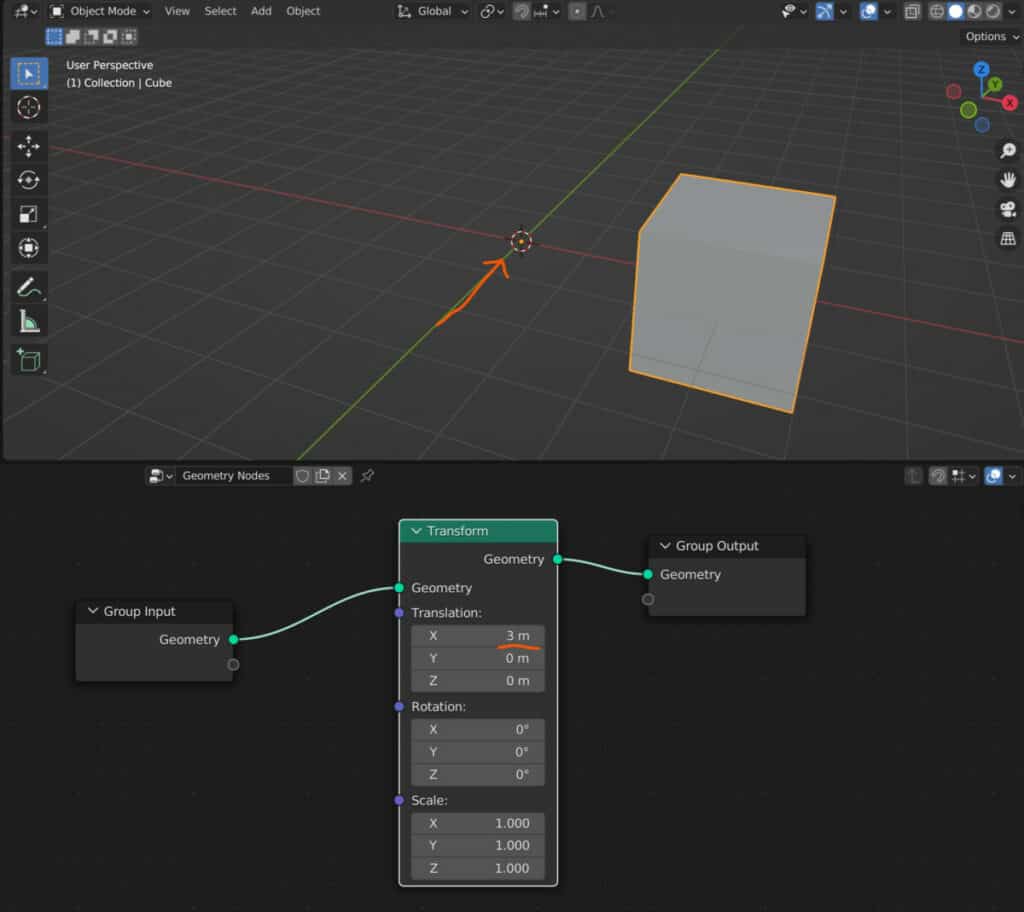
When you begin manipulating these values, such as the location, you will notice in the viewport that the object’s origin does not move.
This is because our geometry node system acts as a modifier for the geometry itself. In other words, it focuses on the mesh data, not the object data of which the object’s origin is a part.
So when we use the transform node, it is more similar to manipulating the location, rotation, and scale or bar geometry in edit mode than when manipulating those parameters in object mode.
Using Multiple Transform Nodes To Change The Behaviour
When using a single transform node to manipulate our object’s location, rotation, and scale, they will act independently of each other.
So we could, for example, move our objects on the X axis, and then if we were to rotate it on an axis, it would still rotate around its own center even if it has been moved away from the object’s origin.
But what if we wanted to manipulate our scale or rotation based on the new location value? Well, we can do that by adding in a second transform node.
You can add a second transform precisely like you did the first, and this time position the second transform between the 1st and the group output.
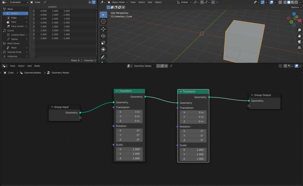
Typical data flow in a procedural system has our information going from one end, which in this case is the group input, to the other end, which is the group output.
When we add a second transform node, that transfer node’s geometry input uses the data it gets from the first transform, not the data from the group input.
This means that any of the changes we made in the first transform node will affect how the second transform affects the object.
For example. Let’s move a cube by three meters on the X axis using the location of the first transform.
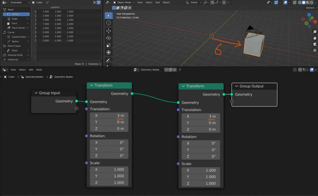
If we were also to use a value of three meters on the X axis of the second transform, then it would be an additive operation where we would add free to free, meaning that our cube would be positioned at six on the X axis.
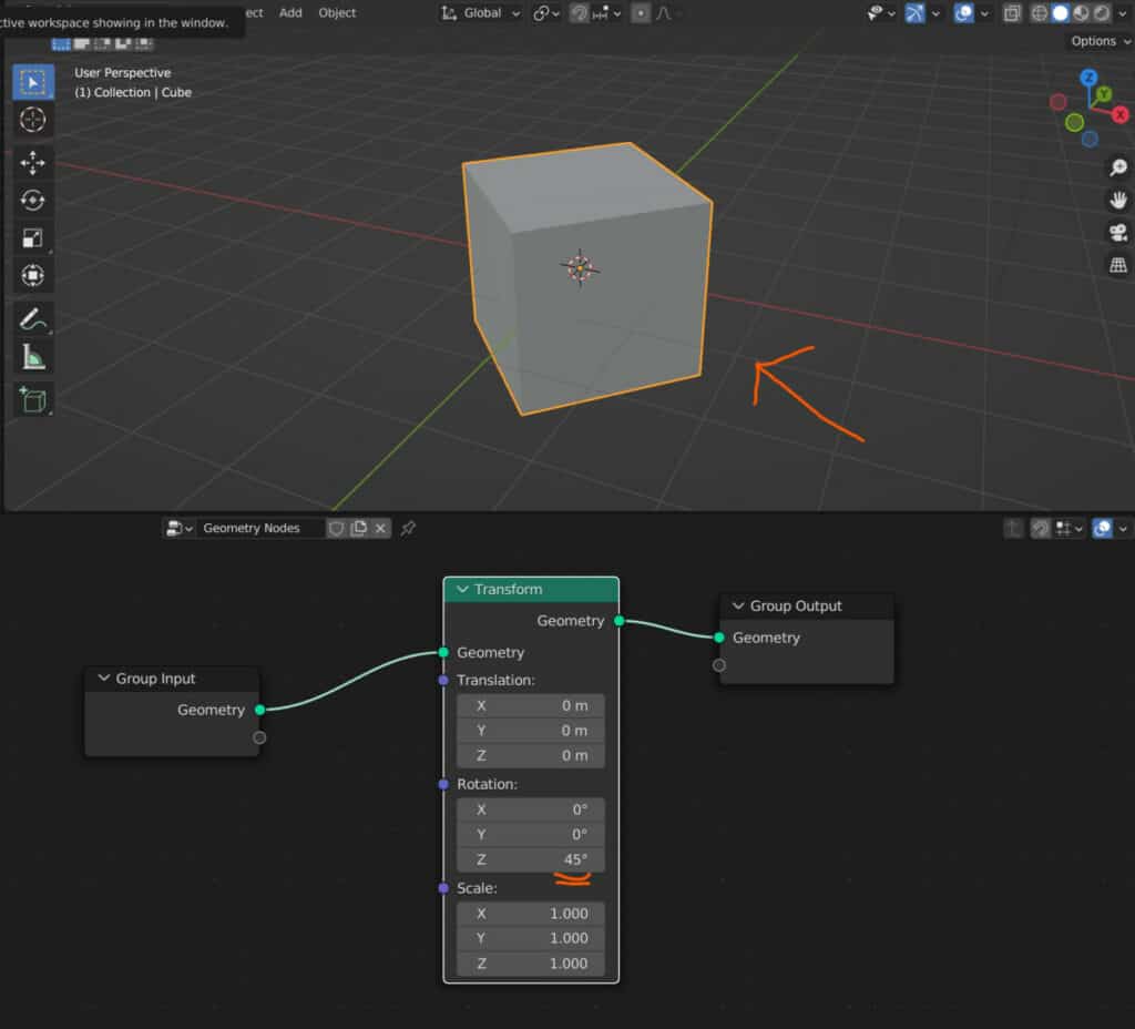
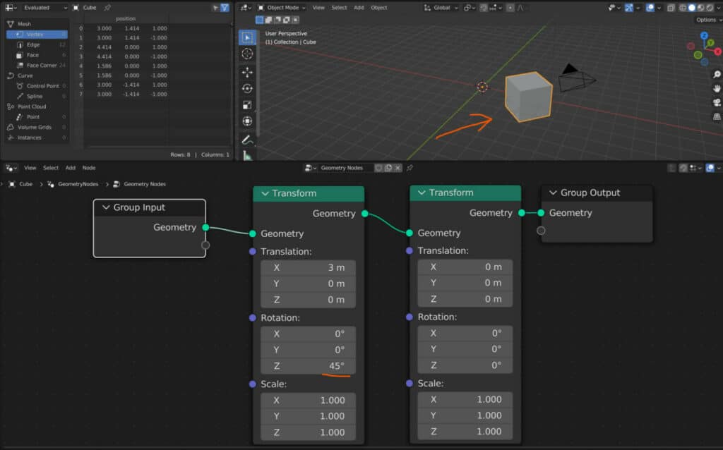
But what about if we were to combine different parameters? If we were to move our objects by a value of three on the X axis in the first transform and then change the rotation on the axis by a value of 45 degrees using the same transform node, the two operations would work independently of each other.
However, suppose you were to rotate by a value of 45 degrees on the Z axis in the second transform node instead. In that case, the behavior is entirely different as the entire object begins to orbit around the object’s origin.
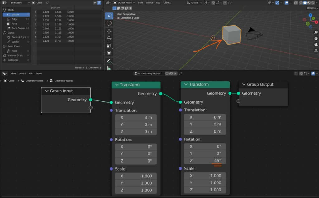
This behavior is also the same for the scale. If you use the first transform node to move your object’s geometry away from the origin point, then the second transform’s rotation and scale will act differently.
Thanks For Reading
We appreciate you taking the time to read through this article, and we hope you now understand how to use the transform node in geometry nodes. If you’re interested in learning about other geometry nodes, look at some of the articles we have listed below.