For the past few years, there has been a lot of talk about what the future of 3D modeling is. And the general answer is that the future of modeling is procedural. In Blender, procedural modeling takes the form of geometry nodes.
Geometry nodes work as a tree of connected data blocks that can be combined in various ways to create 3D objects and scenes. These blocks of information can then be manipulated and repositioned to change the final output of the result using a non-destructive procedural workflow.
Well, it remains important to learn about the traditional methods of 3D modeling. It is becoming more and more important for new 3D artists to learn the best workflows bought creating objects and scenes in applications like Blender. The introduction of geometry nodes offers an entirely new way of creating such objects and scenes.
What Is The Node System In Blender And How Do Nodes Work?
For many years in Blender, we have been able to create materials using one of two methods. The first method was to control our attributes for those materials in the properties panel. The second method was to use the node system of the shader editor.
This flexibility has recently been introduced to traditional 3D modeling workflows. In addition to being able to create your 3D models in the 3D viewports, we can now create both objects and entire scenes by using a number-based system. So what exactly are these nodes?
In Blender, a node system is a combination of different blocks of data, and each block of data can have inputs and outputs. We can use these input and output sockets to connect the nodes together. Eventually reaching a special node known as an output. That output will send the data gathered from that entire node tree to the object or scene.
Each node that we have is built for a unique purpose and has its own set of values and attributes. Changing the values of a single node can change the result of your 3D model. Changing the way that your nodes are combined together is another way of changing the object’s geometry and its appearance in the 3D viewport. As a result of this, there is a limitless number of ways in which we can create objects and even entire scenes using geometry nodes.
A minimum of three nodes will be required for any object that you want to create. One of these is always going to be the output node, and then the second is going to have data that is going to be used to construct the shape of that mesh.
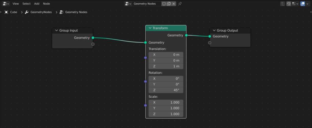
The third node, which is actually going to be the start of the chain in the geometry node setup, is your group inputs. This inputs the data from your existing objects. However, if you are not using the existing object then it is not a strict requirement to use the group input node. However, it can be very useful in other cases as we’re going to look at shortly.
The more nodes that you have, the more potential that you create for your objects, but at the same time you also increase the complexity of the note tree, which makes it more difficult to follow and understand your setup.
If you add a node to your tree, but you do not connect it to any of the other nodes, then that specific block of data or node is not going to have any effect on the output. Every node must either directly or indirectly be connected to the output node in order for its data to be displayed in the 3D viewport.

If you want to edit materials using the node editor, then you can go to the shading Workspace tab located at the top of the blender UI. If you want to use nodes to edit the geometry of your model, AKA geometry nodes, then you can go to the geometry nodes Workspace tab located again at the top of the user interface.
The Main Difference Between Traditional Modeling And Geometry Nodes For Object Creation
There are a lot of differences between traditional 3D modeling and the use of geometry nodes for creating objects in Blender.
The most important difference between the two is that geometry nodes follow an almost entirely procedural workflow.
When you make a change with traditional modeling tools, those tools are normally destructive in nature. The process of constructing your objects follows a very linear pattern, with one tool being used after the next, and the only way to reverse it is to use the Control + Z key to undo your previous operations.
That’s not to say there aren’t procedural tools in traditional 3D modeling. In Blender, we have the modifier stack that allows us to create our objects using procedural versions of our tools.
If at this point you’re not sure what the term procedural means, it represents the use of mathematical equations and values in the form of nodes to generate an infinite number of outputs for a specific object or scene.
If using nodes for materials, then the definition of procedural is to create an infinite number of different patterns and textures for said materials.
In other words, when we use the term procedural in Blender, we are talking about a kind of workflow that allows us ultimate flexibility in what we want to create. And it also allows us to make changes in real-time without destroying the model order material. If we make a change and we don’t like it, we can always go back to the original values that we altered.
What Can You Do With Geometry Nodes In Blender?
The geometry node system is at this point fairly new and is only been about for a few versions of the blender software.
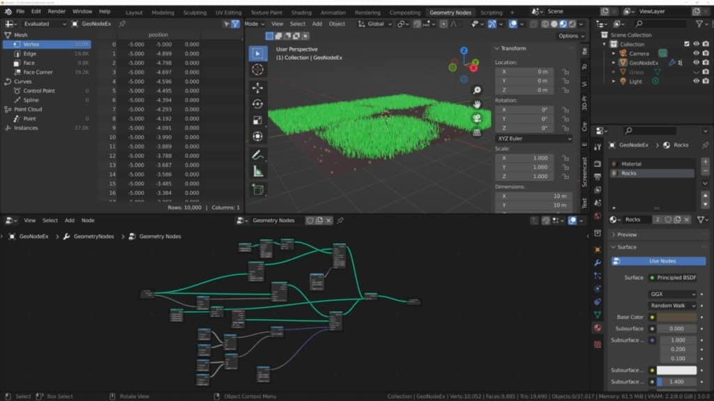
As for version 3.0, however, there is a lot that you can do with geometry nodes. Right now, the strongest feature for geometry nodes in Blender is the ability to instance objects so that you can create incredibly detailed scenes using a very small amount of data.
For example, you can use geometry nodes to instance a collection of rocks on grassy terrain. This allows you to dramatically increase the amount of detail of your environment.
Previous methods of creating these kinds of environments included the use of particle systems, which at this point is out of date and much more difficult than just adding in a couple of nodes for your geometry node setup.
You can also use the geometry nodes system as a means of designing 3D models from scratch. You don’t even need a basic model to start working with, as you can use nodes like the cube node for example to add in the geometry of primitive objects and then use other nodes like the Boolean or object info nodes to begin manipulating the base geometry.
It should be noted that as of the time of writing this article, geometry nodes are not perfect when it comes to the complex creation of more detailed objects, and you are probably better suited to using other toolsets. Like the sculpting workflow, if you are looking to create highly detailed models.
However, if you understand how to use geometry nodes, there are a limitless number of ways in which you can work around this. Keep in mind that when using geometry nodes, you’re working with an entirely procedural workflow.
So even if it may take longer to reach your target appearance or target object, it will also be much easier to make changes if you decide to go in a different direction.
The Different Types Of Geometry Nodes And What To Use Them For
As of Blender version 3.0, there are a wide variety of geometry node types that you can use to construct your objects and scenes in Blender.
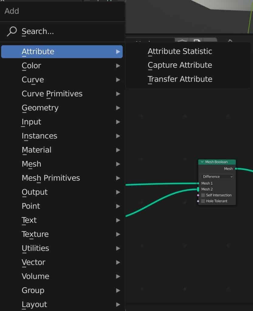
If you go to the geometry nodes tree in your project and then use the hotkey Shift + A, you will bring up the add menu for your notes and you will be able to see that they have been categorized based on type.
Below is a list of the various types of geometry nodes that are currently available to use…
- Attribute
- Color
- Curve
- Curve Primitives
- Geometry
- Input
- Instance
- Material
- Mesh
- Mesh Primitive
- Output
- Point
- Text
- Texture
- Utilities
- Vector
- Volume Group
Creating Entire Scenes In A Matter Of Minutes Using Instances
One of the more powerful ways to use the geometry node system is to create instances of an object and spread them out across a specific area.
For example, let’s say we were looking to create a classroom where we would need to set out tables for each student.
We would start by adding a plain object which is going to be used for the geometry node system. If we wanted to be as procedural as possible, we could use a transform node and then scale up our plane object on the X&Y axis, or we could use a grid primitive node and ignore the base geometry altogether.
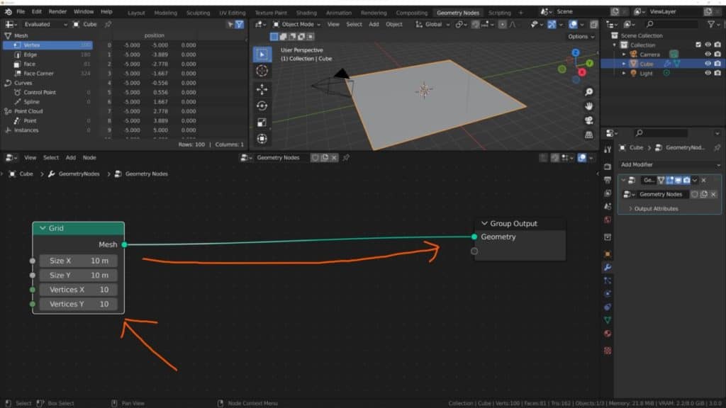
In order to position our instances for our objects onto the plane, we’re going to need some additional geometry, so we can then add a subdivide mesh node after our transform, then increase the number of levels.
Note that we don’t have to use the subdivide mesh node as we can also use the vertex count on the grid node.
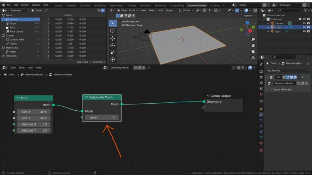
This gives us a larger plane to work with and extra geometry to boot. Next, we can press Shift + A, and in the search bar type in instance on points. Select the node that comes up and add it to your node tree. This is what is going to allow us to instance our table object onto our plane.
Connect the mesh output from the subdivide mesh node to the points input of this instance on points node.
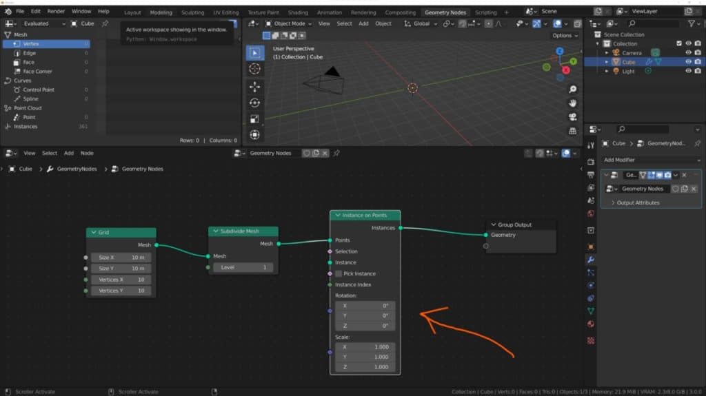
The geometry of your model is going to disappear here, but that’s OK because Blender is trying to replace your geometry with the instance. We have yet to define these instance objects, however, so we’re going to add another node called object Info.
Connect the geometry output of the object info node into the instance input of the instance on points node.
In the empty box of the object info node, left click and it will display a list of all of the other objects in your scene. Select your target object.
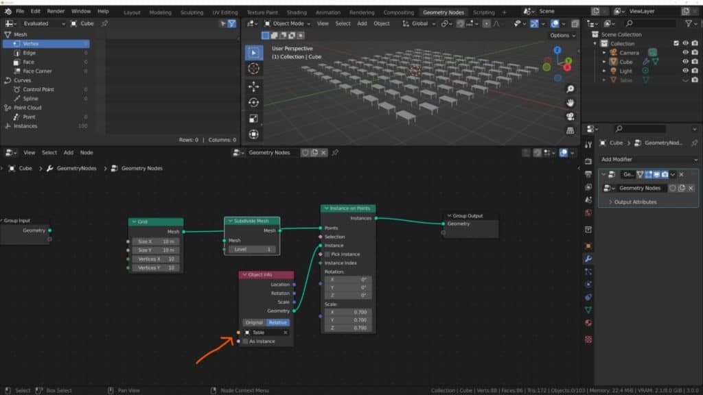
As soon as you do this, Blender will position instances of your target object onto each of the points that were created using the subdivide mesh node.
It looks as though in our example we have ended up with too many tables. But that’s not a problem with our procedural workflow.
We can easily reduce this by lowering the vertex count, or by getting rid of the subdivide node. In a normal classroom with two students per desk, we would need 15 tables. So a 3X5 setup would do.
Get rid of the subdivide mesh option and set the grid X value to 3 and the Y value to 5. We now get a better result just by changing a couple of values.
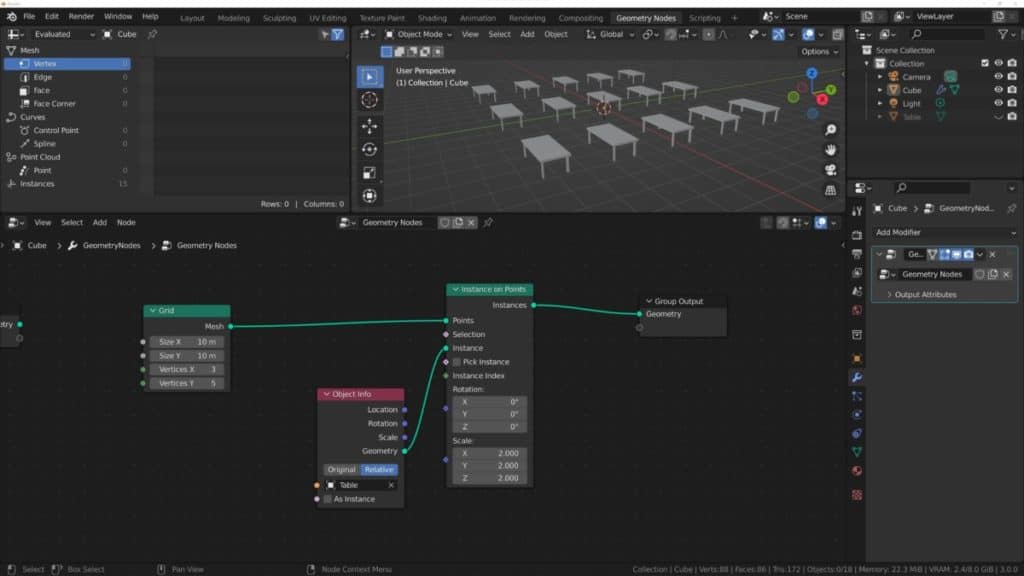
You could then add a second plane object to act as your floor and just position your instanced objects on top of that floor and you have the table set up for your classroom.
This is a very basic example of what you can do by instancing objects in Blender to create an entire scene in a matter of minutes.
Of course, there is a lot more that you can do with these nodes, including replacing your object info node with a collection info node and using a collection of objects as your instance instead.
For example, you could create a collection of a table and two chairs. You can then use that collection in your collection info node and instance it across your scene.
How To Create A Simple Object Using Exclusively Geometry Nodes?
Using geometry nodes to create instances is a powerful use case for the type of modeling workflow that it provides. But what about if you wanted to create just a simple 3D object using nodes from this setup?
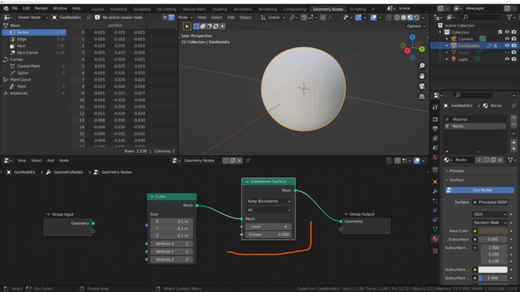
For example, we’re going to create a bowl, while using any primitive object as the base. To start off with, we’re going to add a new note tree for our base object, and then we’re going to open the add menu. Go to the mesh primitives, type, and select cube from this list.
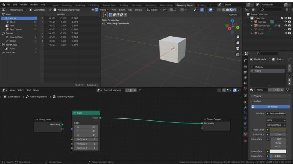
Instead of connecting the cube node to our current setup, we’re just going to position it somewhere in our scene. And then we’re going to take the mesh output and we’re going to plug it into the group output node.
This means that we are replacing the group input with the cube node, the group input node will be disconnected from the setup. However, this is the one node that we can have in our setup and not have it connected up to anything to start with.
Having a mesh primitive node like the cube node allows us to add in primitive objects like cubes, spheres, et cetera. But we have the added advantage of being able to edit some of the core properties of these primitive objects whenever we want to make a change to them.
For example, with the cube object, we can manipulate how many vertices it has on the X, Y, and Z axes. This is something that you cannot do when adding a cube object traditionally.
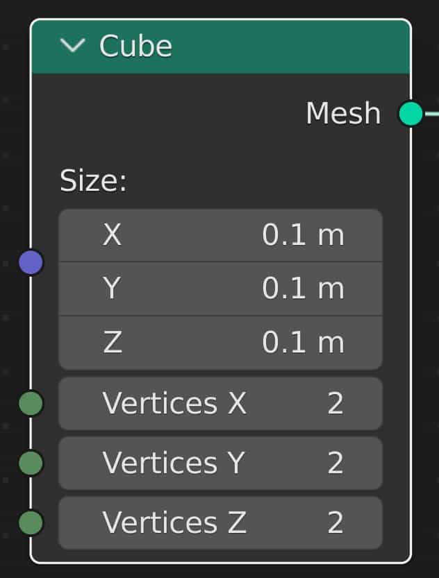
Let’s reduce the size of the bowl on the three axes X, Y, and Z reducing it from 1 meter to 0.1 meters. This gives us a relatively decent starting size for our bowl object, but don’t forget because this is all procedural, we can edit this further down the line.
Next, we’re going to turn our cube into a sphere object. To do this, we’re going to add the subdivision surface node, so press Shift + A to open up your add menu, then go to the Mesh menu and select subdivision surface. Increase the value of the level to four to add more smooth geometry.
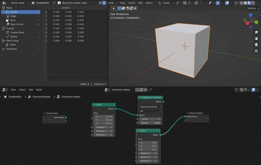
Next week, going to delete the top half of our cube object, which now looks like a sphere. To do this we have to add a couple of nodes starting with another cube node.
This cube mesh is going to be our boolean and we need to view the positioning of our Boolean first. So connect the cube mesh directly to the geometry of the group output node. This is just a temporary measure so we can see what we’re doing.
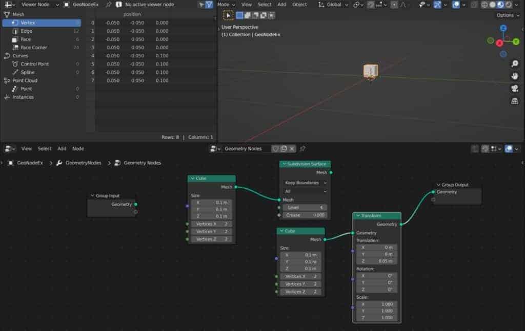
To get rid of the top half of the sphere, we’re going to need to reposition the cube object, so add a transform node and position it after the cube node.
Then increase the value of your cube nodes Z axis location, until you can see that it is in a position where it would cover the top half of your objects. Note that in this case, the Z value should be equal to about half that of the size of the cube. Also, make sure that the second cube has the same size values as the original.
The next step is going to be to add the boolean mesh node, so press Shift + A to open up your add menu once again and this time go to the Mesh menu and select mesh boolean.
This should be positioned just before the group output note. Take your connection noddle from the boolean object and plug it into the Mesh 2 input.
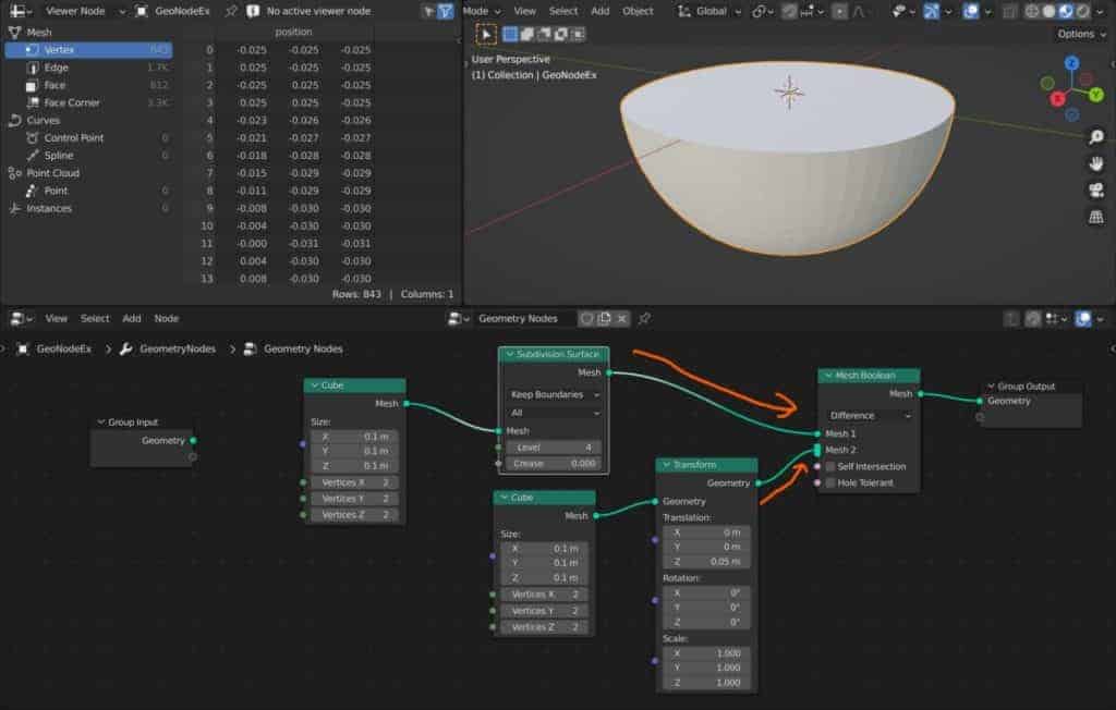
In the mesh Boolean node, you should have a mesh input and a mesh 2 input. Connect the subdivided cube to the top mesh inputs and then connect the transformed cube to the second mesh input.
With the boolean type set to difference, you should now see that the Boolean has taken effect and the top half of your sphere has been deleted from view.
While this may seem like a longer approach to traditional modeling techniques, you have to remember that it is also procedural. We can manipulate the cube object however we want, repositioning it to change our booleans effect. We could even change the cube to another mesh entirely to create a completely different boolean if we chose.
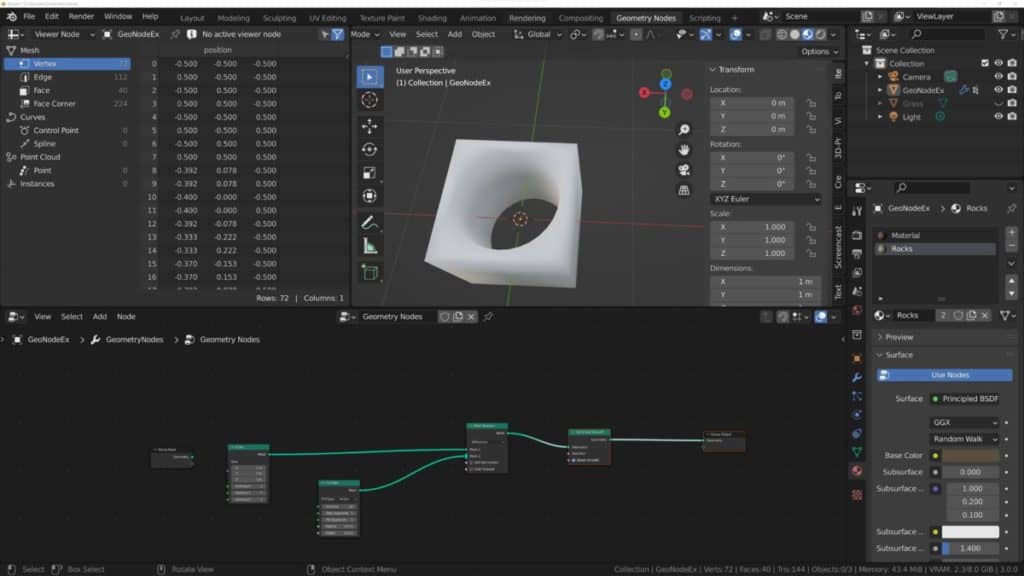
But one more thing that we’re going to have to do is get rid of the center thickness that we can see with our half sphere. We’re looking to create a bowl so the sides should have a degree of thickness, but we shouldn’t see any geometry in the center.
Fortunately, the mesh Boolean allows you to select multiple objects to act as your booleans for the main model. If you take a look at the mesh boolean, you will see that the mesh two input looks slightly different from the mesh one inputs.
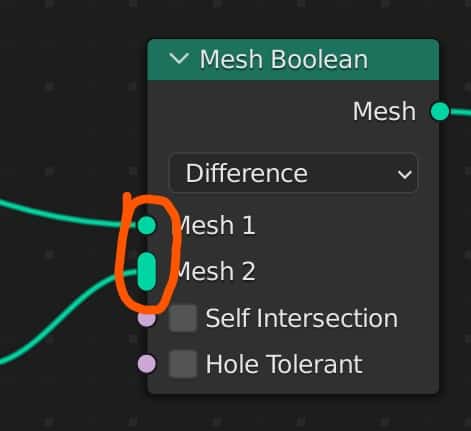
The longer-looking socket indicates that it can take in multiple noodles at the same time. We are going to use the original subdivide cube as the base for our second boolean here. Add a transform node to your setup, but don’t connect it to anything just yet.
Just position it roughly in between the subdivision surface node and the Boolean node. Left-click and drag from the mesh output of the subdivision surface node and connect it to the geometry input for the transform node.
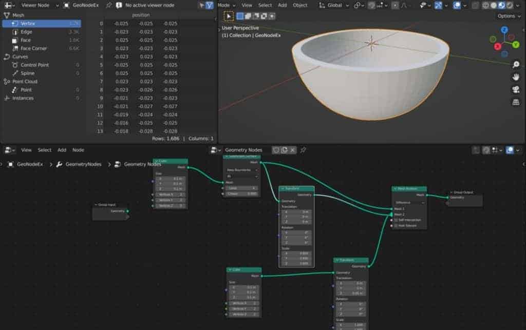
Decrease the scale values on each axis to something lower than one. Then connect this transform node that you have created to the mesh two input of the boolean node. You should now see that we have created a hollow bowl as a result of the additional boolean.
This is an example of combining your nodes in various ways to create objects using the geometry node system.
Using Geometry Nodes As A Modifier For True Proceduralism
What you may not realize initially is that the geometry nodes system is actually just a means of manipulating a modifier.
When you add a geometry node setup to existing objects go to the properties panel and then go to the modifiers tab. You will find that a geometry notes modifier has been added to your objects.
What’s amazing about this type of modifier, however, is that you can actually edit the attributes that you see in this modifier tab. What you see here comes from the input of your tree. For example, let’s say you sent to change the level of detail of your subdivision and the bowl thickness as a modifier.
You can take the input of your Subdivide node and plug it into the group input node. For the thickness, we can use a combine XYZ node to use a single value for our vector, and then plug each axis into a new socket of our group input.
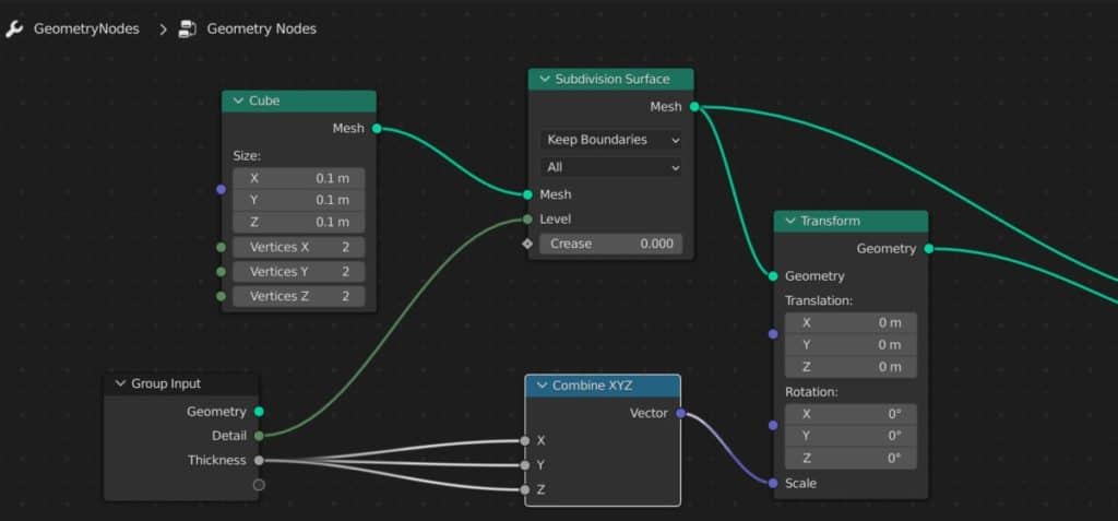
When you connect these nodes in this way, the values will appear in the modifiers tab. You would then be able to edit these specific values from either the geometry nodes tree or the modifier itself.
Any value in your no tree that has an input socket can be connected up to your input node. And can therefore be edited from the geometry nodes modifier.
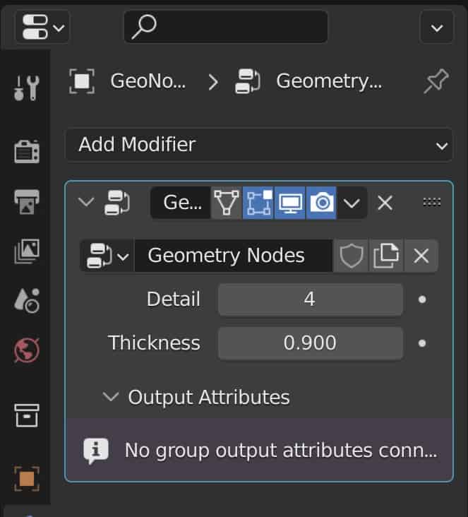
This is what gives geometry nodes each true power as a procedural tool because you can take the values that you want to be able to change and connect them to the input node so that you can manipulate these values from the single and simple Modifies tab instead of the more complex node tree.
Thanks For Reading The Article
We appreciate you taking the time to read through the article and we hope that you have been able to locate the information that you were looking for. Below we have compiled a list of additional topics that are available for you to view and learn more about Blender.
-
Symmetry for Hard Surfaces in Blender
Ensuring symmetrical perfection in hard surface models with Blender.
-
Detail with Shrinkwrap: Blender Modelling
Achieving intricate detailing with Blender’s Shrinkwrap modifier.
-
Edge Loops for Hard Surfaces in Blender
Utilizing edge loops for defining crisp hard surface details in Blender.