The cool new way to create 3D models and even entire scenes using applications like Blender is to create them procedurally. That means to be able to construct something that can be edited an infinite number of ways. In the case of Blender 3D, this means using geometry nodes.
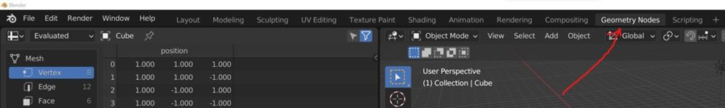
To access geometry nodes in Blender, go to the top of the blender interface where you will find the workspace tabs. Towards the end of this row is going to be the tab for the geometry nodes workspace. Left-click on this tab to open up the workspace.
Within this workspace, you will be able to create entire scenes using nodes as your building blocks. You can then make changes to these nodes to procedurally generate an infinite number of results for your models in Blender.
What Can I Do With The Geometry Nodes Workspace?
As with many of the other workspaces in Blender 3D, the geometry nodes workspace is designed so that it can be the optimal location for those of you wishing to create procedural objects.
All of the panels that you will find within the geometry nodes workspace allow you in some way to improve upon your procedural designs. The most obvious editor here is going to be the 2D Viewport, which will allow you to visualize the results of your node systems.
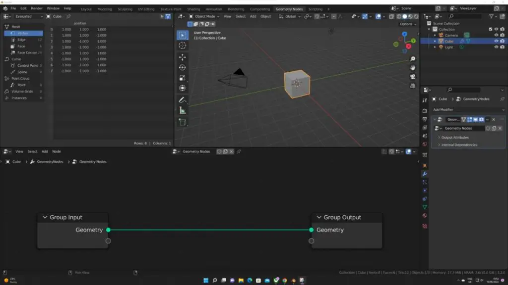
Directly to the side of the 3D viewports, however, is an editor that is used primarily for geometry nodes, and one that you may not have noticed anywhere else in Blender, and that is the spreadsheet.
We can still use the 3D viewport how we normally would, constructing our singular objects and our scenes using our more traditional methods. When working with geometry notes, however, the viewport is more for visualizing what is going on in our no trees rather than actually editing our models.
Of course, that’s not the only panel that we have access to within our workspace.
What Is The Spreadsheet?
The spreadsheet stores various types of information relating to the geometric structure of a selected object. It can be used in traditional 3D modeling as well as using procedural methods like geometry nodes as it’s purely there to demonstrate the data itself to the user.
The spreadsheet is divided up into various types of geometry, ranging from mesh types to curves, to instances.
Within each of these geometric types, we have what are known as domains and domains are there to divide up our different types of data into their specific forms.
For example, under the mesh data type, we have the point, edge, face, and face corner domains. The point domain houses the information for our vertices, while the edge domain houses information for the edges.
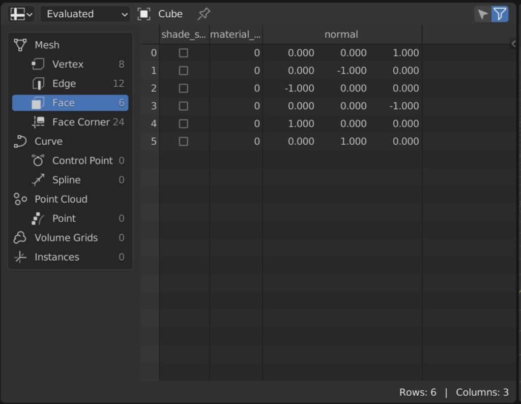
Following that trend, we also have the face domain, which stores information relating to the faces that are created for our objects.
We then have the face corner domain which is specified to the corners of those faces rather than the actual points. These are used primarily for UV mapping.
Selecting any of these domains would allow you to few the information that is stored within that respective domain. For example, if you were to choose the point domain, you would be able to see information regarding all of the points or vertices used to construct your mesh objects.
The list that you will see within the spreadsheet when you access to domain will feature all of the elements stored in that list. For example, with the face domain, all of the items that you see within that list are individual elements or individual faces of the model. The same is true for any domain, including edges and points.
Each of these points is separated into a list and each point is given an index value unique from the other points. The index value is an example of an attribute. Attributes are the various forms of data that allow us to actually control our elements using nodes.
In the case of point elements, we have the index value that is used to define each individual point on our object, but we also have a position attribute here that allows us to view the exact location of each element.
Different timelines are going to use different attributes to control those elements. For example, the face corner domain uses the UV mapping attributes.
The Outliner And The Properties Panels
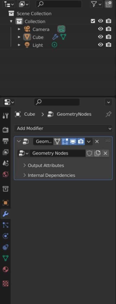
As with the large majority of workspaces that you can access in Blender, the outliner and the properties panel are accessible here in the geometry nodes workspace.
The properties panel is important here because it allows you to access the geometry nodes tree in its real form, which is as a modifier. When you create a new geometry node tree, a modifier will be added to your object and you can access this by going to the modifiers tab.
As you begin to adapt to the use of geometry nodes, you will learn how to expose the parameters of your nodes to your group input, allowing you to use them within the modifiers tab of the Properties panel.
The outliner panel is used purely to organize the scene using the outline hierarchy and is useful if you are looking to perform basic functions within the 3D viewport, such as selecting objects or hiding them from view.
The Node Editor Used For Creating Our Procedural Models
The last panel here that is immediately accessible to us in the geometry nodes. Workspace is the geometry nodes editor itself.
If you have used other node systems within blender, such as with compositing or with materials, then you will have a very good idea as to how the node editor works for procedural models.
By default, this system is going to be blank with no nodes assigned to the objects, mainly because we have yet to assign a node tree.
Click on the new button that is located in the header bar of this tab and two nodes will be introduced to set up a group input and group output node.
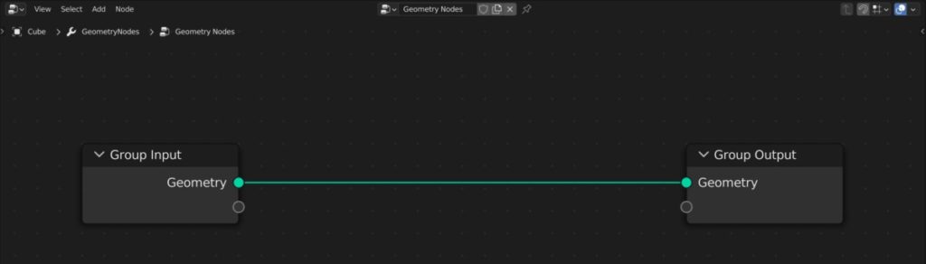
The group input stores the original information of the object that the geometry node system has been assigned to. It can also be used to expose parameters from other nodes so that they can be used in the geometry nodes modifier within the properties panel.
The group output node on the other hand will store the result of all the changes made using the node system, and will then project that result onto the objects within the 3D viewports.
From here we can begin adding notes by going to the add menu or using the shortcut Shift + A to bring up the same menu. Then we can begin adding nodes and creating our objects using our node systems.
The Best Place To Learn Geometry Nodes?
Geometry nodes differ from the traditional form of modeling as it acts as a system that the artist can control to both create and change the models in their scenes. The best way to learn this system is by using our own.
The Blender boot camp is an educational resource dedicated to teaching Blender and Blender alone. The geometry nodes boot camp is our tailor made course to learning the node system from the ground up.
If you are looking for the best resources to get you started though, we are offering our free geometry nodes starter kit, which contains our beginners guide to geometry nodes along with our procedural building asset pack and geometry nodes terminology cheat sheet.
Learn More About Geometry Nodes From These Articles
We hope that you find this article useful for accessing the geometry nodes system. If you want to learn more about how you can use geometry nodes, then check out these articles listed below.
- A Beginners Guide To Using Geometry Nodes
- Which Version Of Blender Has Geometry Nodes
- How To Use The Group Input And Group Output Nodes
- What Are The Different Types Of Attributes In Geometry Nodes
- What Are Fields And How They Affect Object Creation