Over time you will begin to use the geometry nodes system in new ways as you explore the multiple layers of complexity to the node system. One of the key learning points for anyone learning geometry nodes is to be able to use attributes, and amongst these attributes we have the vertex position.
The position attribute can be called when using the position node and then connected to a node input. For example, a position node can be connected to an extrude mesh node selection input, and then a math node can be used to define the selection based on the position attribute, controlling which areas of the model are extruded.
When working with attributes we can better manipulate how our geometry behaves using the node system. Not only can we control the positioning of our vertices but we can also use the current position data to define our selections for other nodes.
What Is The Position Attribute When Working With Geometry?
When working with objects in Blender we focus primarily on four of the objects main properties, which are the shape (how the object looks) and the three transforms (Location, Rotation, and Scale).
Sometimes when watching a tutorial on YouTube you may hear the term position instead of location when referring to where an object is placed.
This can be slightly confusing as while the two terms are very similar they are not interchangeable and are used in different scenarios.
The term location is used to refer to where an object is found in the 3D viewport. This means that the location is associate to the object data rather than the mesh data.
On the other hand, the term position is correctly used to define where mesh geometry is located in the viewport. For example, the coordinates of a single vertex relate to the geometry’s position.
Where To Locate The Position Of Our Geometry In Geometry Nodes?
So in geometry nodes, the distinction between location and position is made more clear cut as the position is referred to far more often than location when we are working with our node setup.
This is because when we use geometry nodes we are manipulating the shape of the model rather than transforms.
The exception to this rule is the use of the transform node which is used to replace the functionality of the transform tools in the viewport. However this node still only affects the object at the mesh level and does not affect the actual location of the object.
We can locate the position data of our geometry by going to the spreadsheet, which is found in the top left corner of the interface when using the geometry nodes workspace.
To the side of our spreadsheet, we have a table of the various types of data that our geometry nodes can possess, ranging from mesh to curves, to instances.
Within each type we have the domains associated with it that divide up our geometry types into more specific categories.
For mesh data we have the Vertex, Edge, Face and Face Corner domains.
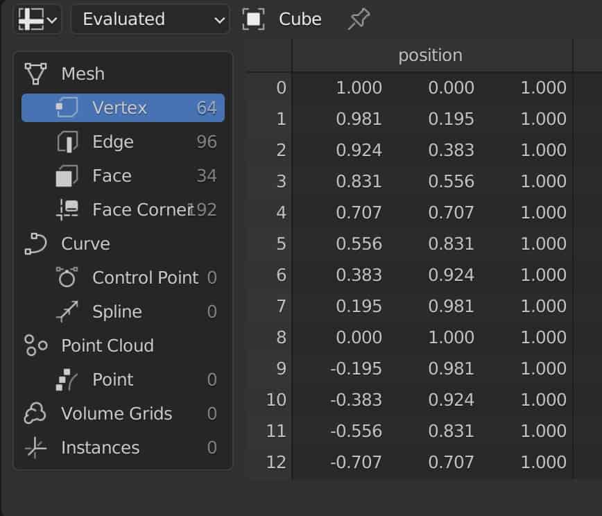
If we select the vertex domain we will see the information associated with all of our objects’ vertices. This will show us 2 attributes that Blender already uses to control this type of geometry.
The index value is a unique identifier for each vertex or point on our model. The position attribute tells us where each point is located in 3D space using vector-based coordinates.
If you want to learn more about Blender you can check out our course on Skillshare by clicking the link here and get 1 month free to the entire Skillshare library.
How To Use The Set Position And Position Nodes?
There are many nodes in Blender where the position attribute can be used as a means of control, and this is most apparent when using the set position node.
Before we go further, we need to stress that the set position node is different from the position node. The set position node allows us to edit the positional data of our geometry, while the position node is an input node used to call the position attribute to define other properties of the model.
This is found in other areas of geometry nodes as well where we have an attribute node that calls the attribute data, and a set attribute node that changes that base data. For example, we have the material index and the set material index nodes, or curve radius and set curve radius.
Using The Set Position Node
Let’s take a look at the set position node in its most basic use case, attaching it to a new node setup. We can see when we assess the properties of the set position node we have the following to work with.
The geometry input and output sockets are standard here and allow the geometry data to pass through the node while of course being adjusted by the other node properties.
The selection input allows us to define the selection of geometry that will be affected by this node. We can use different methods to define our selection, one of which is to use the position node to call that attribute and then use a math node to define the selection.
We could also define selection here using the index attribute of each point, a custom-made ID attribute, or even an entire vertex group.
The two inputs below that can be more confusing, and are the position and offset parameters. So what is the difference between the two as both seem to relate to the position attribute?
The position input is used to define the new position of a defined selection, while the offset parameter allows us to change the actual position of the selection in the viewport.
This does sound the same so how are these two nodes used.
Below is an example of using the offset value to move the top half of a UV sphere up on the Z-axis, with the top half being defined by the selection input.
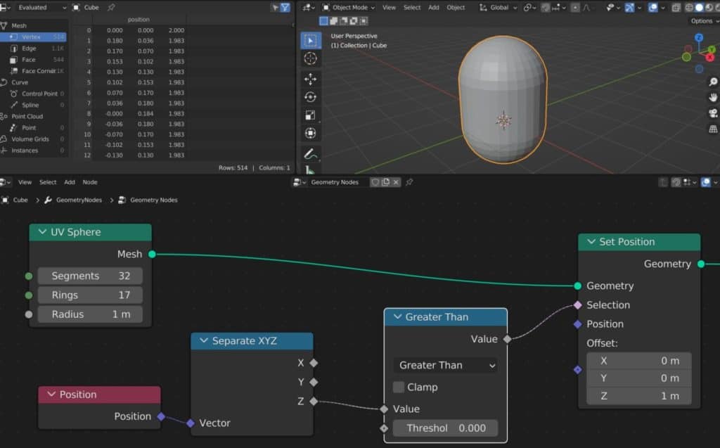
Using The Position Attribute Node
The position attribute node is actually just called the position node and is an input node designed for a single purpose, to call the position attribute.
What does this mean? It means that when we use certain nodes, those nodes use parameters that are searching for some sort of data.
This data can exist either as an arbitrary value, like when using a value node, or from a pre-existing attribute like the position node.
The position attribute can be used with the set position node to control which vertices are influenced by the node. It can also be used with a wide range of other nodes.
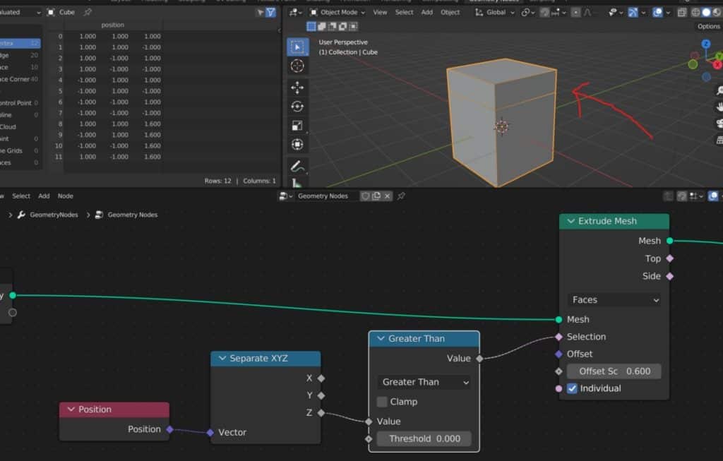
Calling The Position With Extrude Mesh
The position attribute works really well in Blender when connected to the selection input of a node. An example of this is with the extrude mesh node.
In this example the extrude mesh node is used to extrude the faces of a cube. The selection is defined by the position attribute and uses a greater than node so that only the top face is extruded.
Calling The Position With Separate Geometry
Another example of using the position data to define the selection is when we want to separate our geometry.
Below we have a cube that has been subdivided and then reshaped using the dual mesh node to create a diamond-like shape.
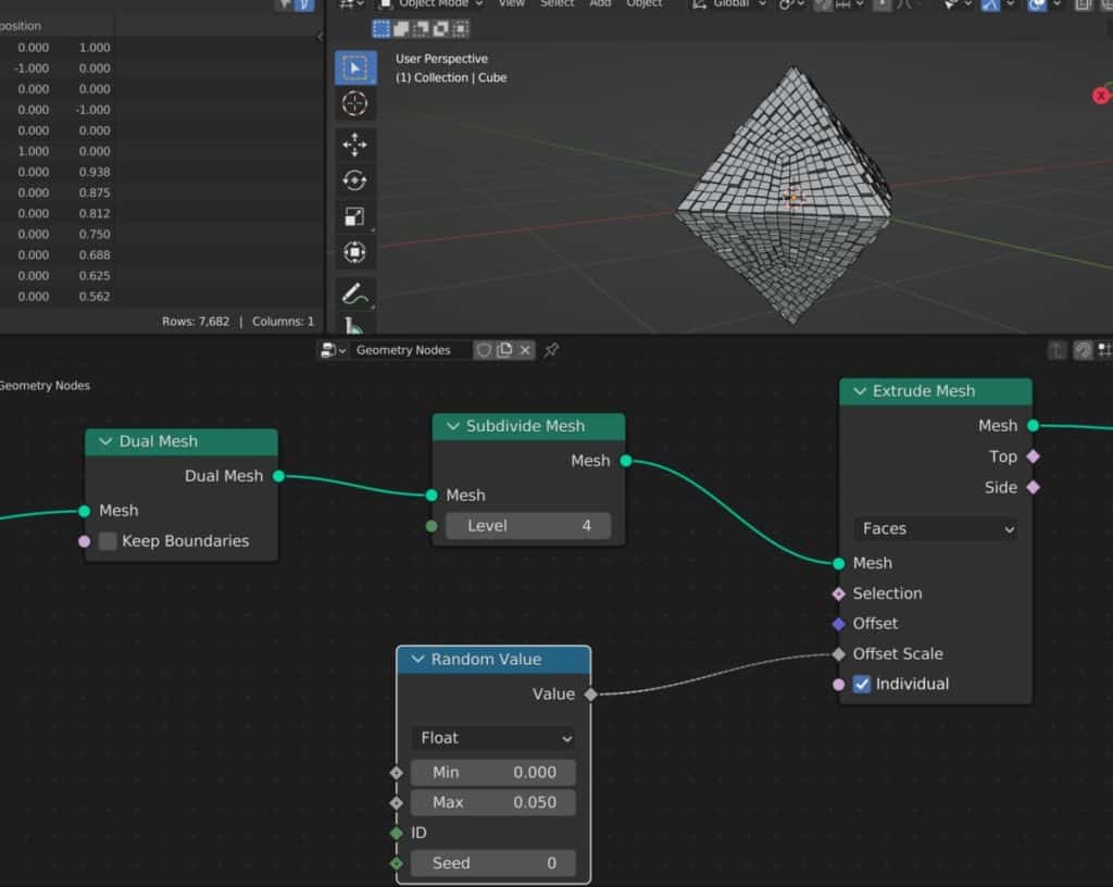
We also created a random extrusion for the faces to give them some more appeal.
The separate geometry node disconnects one half of our model (Selection) from the other (Inverted) and then connects them to different data paths where we can edit each half independently.
For this, we use the selection input to define what geometry falls into what data path. We can use the position node to use that attribute and then define our selection using the separate XYZ node and a math node like we did in the previous example.

Some monitors do not come with their own speaker system, so many of us need to find a good pair of speakers for our audio if we don’t want to use headphones. We use these as our daily speaker system as they offer great quality for the price point.
Creating Custom Attributes To Control Positioning
It is possible in Blender to create a custom attribute to control the positioning of our geometry in Blender. We can do this by creating one of two types of attributes.
The first type is an ID. This is an integer value that can be used to identify either a single element or multiple elements if they have the same ID.
The ID attribute is not the same as the Index attribute, which is a unique integer given to every element within a domain. IDs do not have to be unique and multiple elements (Ex Vertices) can share the same ID.
The second type is a method that will be familiar to traditional 3D artists, and that is the use of vertex groups.
When we add a vertex group by selecting the geometry and then assigning it to a new group in the object data tab of the Properties panel, the information of that vertex group becomes visible in our spreadsheet in the form of vector data.
Once you create these attributes you can then call them to your selection for the set position node.
Thanks For Reading The Article
We appreciate you taking the time to read through the article and we hope that you have been able to locate the information that you were looking for. Below we have compiled a list of additional topics that are available for you to view and learn more about Blender.
-
Sharp Edges in Blender with Crease Sets
Utilizing crease sets for maintaining sharp edges in subsurf modeling.
-
Bevel & Chamfer: Blender’s Edge Mastery
Mastering the application of bevels and chamfers for sharp edges in Blender.
-
Non-Destructive Workflow in Blender
Embracing a non-destructive workflow for flexible modeling in Blender.