In Blender version 2.9 a new type of modeling was introduced to Blend Afridi. That was geometry notes the ability to create your objects procedurally using a node-based system. In 3.0, however, this system was remodeled and fields were introduced for geometry modeling with nodes.
Fields change the way that Blender constructs its node trees, and are often used to introduce geometric data into your geometry node setup. Field nodes can also be used to change that same geometric data. For example, the use of the position node.
The introduction of field noses changed the way that Blender uses its geometry node system, which is still in its infancy. So what exactly are these field nodes and how do they defer from the other form of nodes in Blender?
The Difference Between Data Flow Nodes And Field Nodes
You can divide up the categories of geometry nodes into two separate types. A node can either be classed as a data flow node or a field node. So what’s the key difference between these two different types of nodes?
In general, a data flow node passes through typical geometry data. For example, when using say, the set position, note you can pass in geometric data into the geometry inputs and then pass it out of the node again from the geometry output. This is an example of a data flow where geometry is being passed through the node system.
On the other hand, you have the use of field notes. The simplest way to think about field nodes is that they are used to interpret and change the values of your node system. To alter the final output, for example, you can pass numerous values into a specific node and then convert those values into a single number. That number is used to calculate the geometric data that is going to be passed on.
The easiest way to tell what is a data flow and what is a field is to take a look at the actual node sockets for whatever node you’re using.
If the no socket is circular in shape, whether it be an input or an output, then it’s technically a data flow where data is being passed into the node and then out again for the output.
Fields, on the other hand, have a diamond-shaped socket, for example with these set position nodes we have a circular green socket for our geometry data because it’s part of a data flow system.
But below that, we also have several options that have diamond-shaped sockets to them for things like the selection position and offsets of our data. This is what is known as field data and is used to change the information transmitted from our objects’ geometry.
One node that we can use as an example is the Distribute To Points node. This node is used to convert your geometry into an array of points that can be used as instanced locations for other objects.
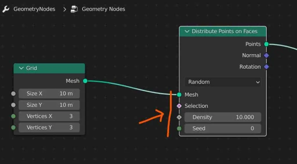
You will see that on the input side we have the mesh input which takes in the data of the mesh object. This is again an example of data flow where data on the object passes through the node tree.
Below that we have the field sockets that allow us to alter the properties of that node. For example, we can increase the density value to increase the number of points that the node creates.
Fields are the primary way to alter the way your node tree works, so in this example, we can change the way the density attribute works by adding nodes to the setup.
The first node is a value node which we plug directly into the density to start with. The value does not change much by itself and is used for data flow, transmitting data from one node to another. We can see this as the value output is a circle.
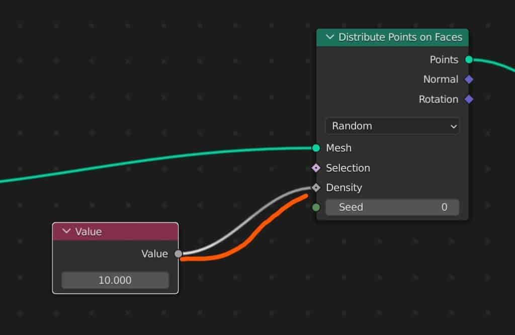
Notice that the value node is a single value, and the density input is a diamond with a hole in it. This shows that the density socket can take either a single value or a field (function).
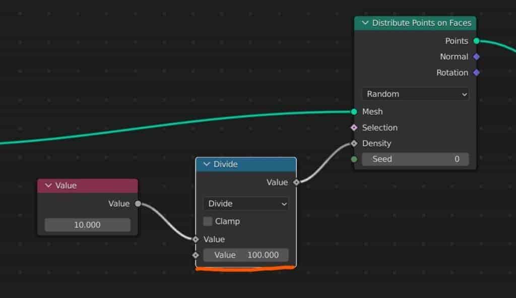
We need to be able to edit this value, which we can do by adding a math node and positioning it in between the value node and the Distribute To Points node.
The density attribute takes the value that you use and multiplies that value by 100 to get the number of points that will be added.
If we want to get a 1:1 ratio between the value and the number of points, we can set the math node to Divide, and set the exposed value to 100. Now, a value of 10 will yield 10 points on the object and not 1000.
This is an example of how fields are designed to work in Blender, changing the way our node tree affects our model.
How To Use Field Nodes In Your Geometry Nodes Setup
Another way of thinking about a field is to refer to it as a function, or a calculation that changes the way a node influences your data flow.
As such, the most common use case of fields is to use math nodes to adjust singular values. Another example is to use the vector math node if you want to adjust vectors that have typically three values, or if you want to control just one of those vector values.
Input nodes are a type of node that typically are used to provide data that fields can use to manipulate that data. In many cases, using value nodes means little, as they are considered providers of data rather than manipulators.
This is the case with the value node, which only allows for the inclusion of a single numerical value which can then be used elsewhere in the node tree for any purpose. That data can also be sent to multiple nodes at the same time.
For Example, we could plug the value node directly into the seed input of the distribute node, which allows us to change the seed value while changing the density, creating a new result each time we change the value.
But to manipulate that value we need to use fields like with the math node, as without the math node to control that value, we might as well not have the value node at all.
Let’s look at a slightly more complex example by adding an instance to points node to our setup, and use a UV sphere node as the instance.
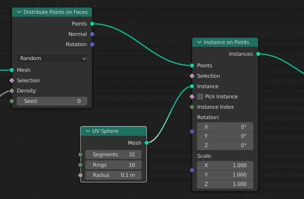
Now all of the instanced points have transformed into individual UV spheres. But what if you wanted to randomize some of the attributes of these properties.
The change to Blender 3.0 has made many of the original nodes, including attribute scale and attribute randomize, obsolete and many of these are no longer accessible to the user. They have been replaced by the field node system.
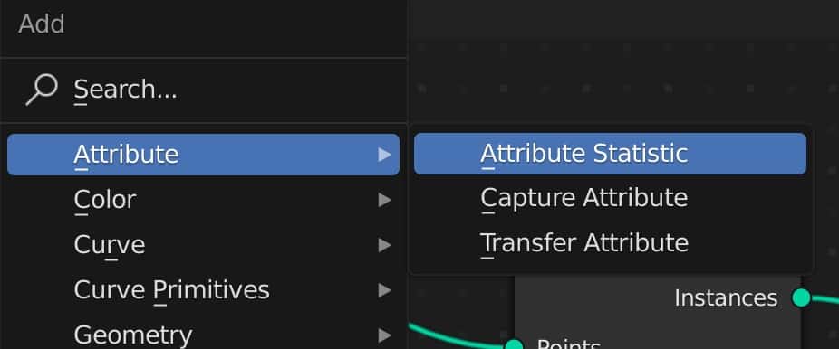
This process has been made much easier by having a more flexible Random Value node introduced. With this node, we are able to create a random value for our field, either as a singular value or even as a vector.
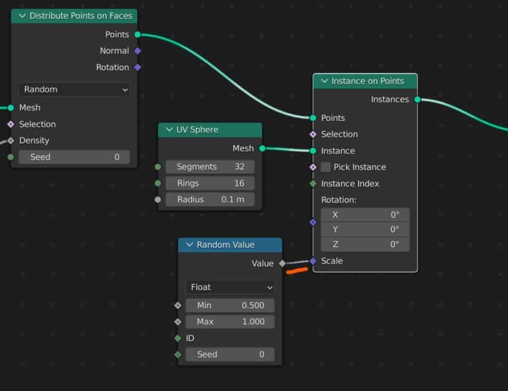
To change the scale of your instances so that they are randomly sized, connect the random value node to the scale input of the Instance On Points node.
Changing the min and max values will alter how much the spheres are allowed to deviate from the original size.
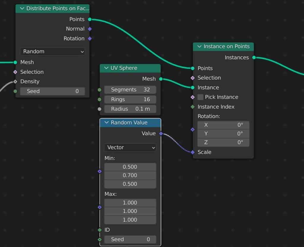
And if you want more control, switching over to vector will allow you to adjust the scale on the X, Y, and Z axes independently.
Using Field Nodes To Create A Scene Through Instanced Geometry
Geometry nodes have often been better suited to creating highly detailed scenes through the instancing of geometry and objects. You will find many youtube tutorials on this kind of workflow for creating procedural and abstract scenes.
Field nodes make it easier than ever to create entire scenes through instanced objects. Let’s look at an example where we create a grassy plane.
The old way of doing this would be to use the particle system from the properties panel, but this is now out of date and using nodes actually makes things easier here.
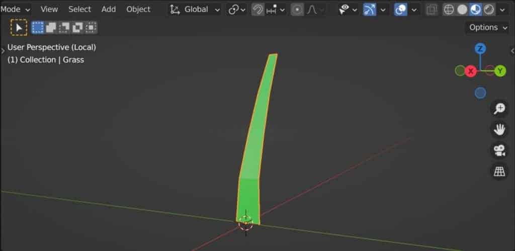
Before we create the plane for the grass to stand on, first create a single grass object. We use a rotated plane and add some loop cuts to shape the plane like grass. Then we give the grass a green material.
Hide the grass object from view and then add a plane object. Also, add a node tree in the geometry nodes tab. The initial setup is similar to what we used above, where we created a grid node and then instanced points to the grid.
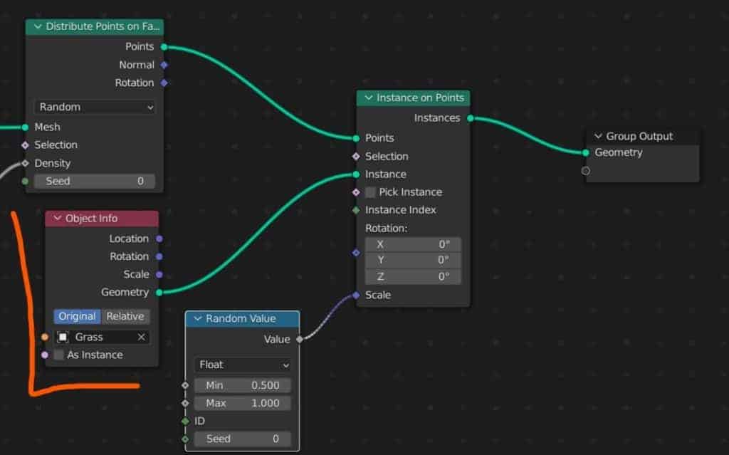
The first key change that we are going to make is to not use a UV sphere node, but rather the grass object.
We can use the object info node in geometry nodes to reference another model. So we add this node and locate our grass object, setting it to relative and connecting the geometry output to the instance input.
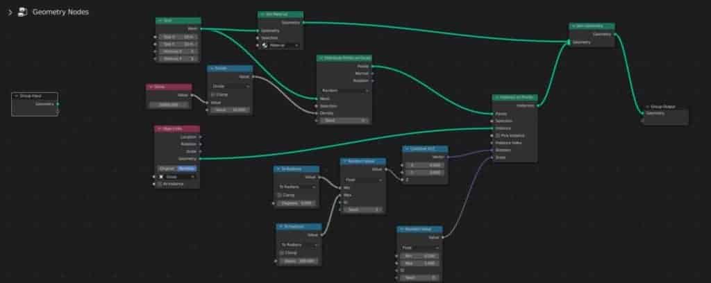
As we are projecting our grass onto the plane, we need to be able to see the plane as well. To do this add a join geometry node to the end of the tree, and connect the instance on points node and the grid node to join geometry as seen below.
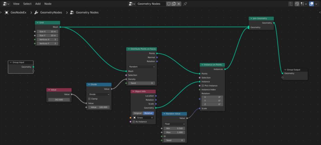
This will allow us to view the original grid mesh as well as the instances. If you add a material to the base object, though, you will not be able to see it through the grid.
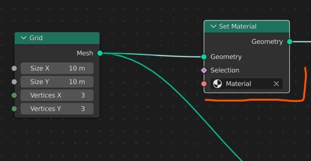
To assign the material to your new geometry, you can add a set material node and add your material that way, making sure to position the node directly after the grid node.
Like in our example before, we can also use the random value here to randomize the sizing of the individual grass instances using the scale.
For a more natural look though, we want to rotate the grass as well, but only on the Z-axis. This is a little bit more complicated but can be achieved using fields.
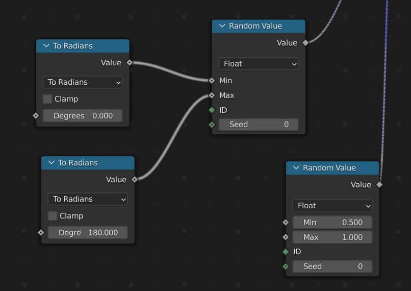
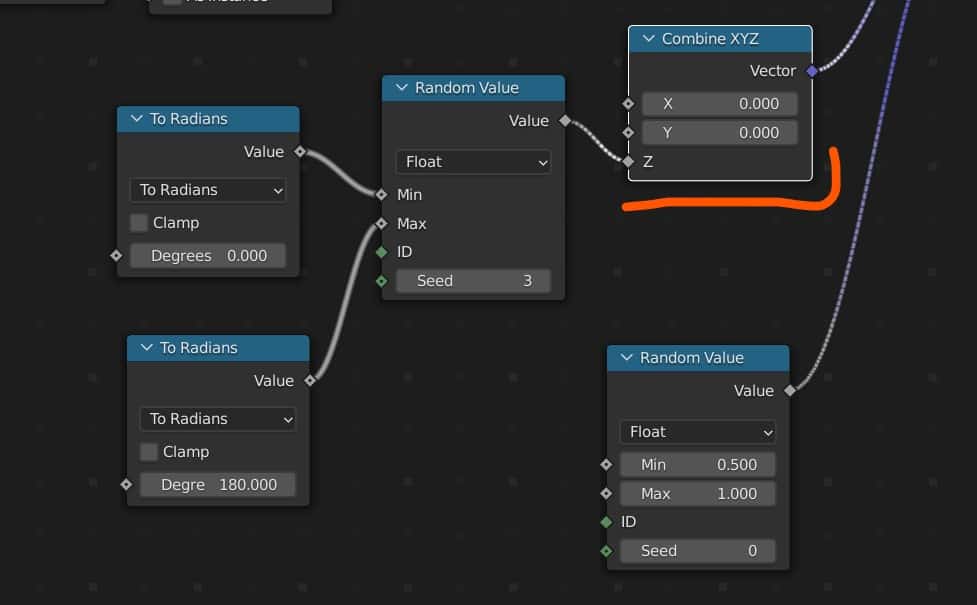
Adding a random value to the rotation vector of our instances has too strong an effect on the result. It also uses radians instead of degrees to evacuate the rotation.
To convert the value to degrees, add a math node before the random value and set it To Radians. Use the degree value that you want and then replicate for both the min and max values.
This way you limit your rotation based on degrees and then Blender converts these values to radians for use in the random value node.
Then we need to isolate the Z-axis only, which we can do by adding a Combine XYZ node and positioning it after the conversion node. Set it up so that the conversion node affects the z value only, and then then you should get a more subtle rotation of your instanced grass.
It takes a few nodes to get to this point, but you can now use your own procedural grass, and manipulate core attributes like its density, scale, and rotation using the fields system.
How Can I See What Is A Field And What Is Not?
Blender allows you to visualize your fields by changing the appearance of specific aspects of the node tree. The most obvious change is the shape of the sockets used.
The shapes can be divided into three forms. The first shape is a circle, which follows a data flow workflow and allows you to transmit single values from one node to the next like with mesh and geometry data.
The second shape is the field diamond. This shape represents an attribute that takes in field data.
The third shape is a diamond with a hole in it. This allows the attribute to read either a field or a single value.
For example, with the density input, we are able to use either a field or a single value. This allows us more scope in what we are able to do, such as being able to isolate areas of the mesh where this density value can affect.
Connect the density to the group output node and then go to the modifiers tab where you will find the geometry nodes modifier. You can then click on the cross icon for the density and select an attribute of the mesh, like a vertex group.
Note that this requires you to use the base geometry instead of a mesh primitive to work though.
When connecting a field from one socket to another, you will also notice that the noodle is different. For normal data flow, the noodle appears normal, but with fields, it becomes a dashed line instead. This is to act as a second visual distinction between the transfer a single value, like geometry, and the transfer of a field or function.
Which Version Of Blender Uses Field Nodes?
Well, geometry nodes as a concept was introduced in Blender version 2.9. The way the geometry nodes operate was changed in version 3.0 to introduce the concept of field nodes to Blender. Because of this, using version two point 92.9 one or 2.92 you would have a baby version of the current geometry notes system that would actually work differently in many aspects.
Because geometry nodes is still a very new concept for 3D modeling in Blender, it is still subject to a lot of change over the next few years. But Blender 3.0 can be considered as the starting point for the common way in which geometry nodes are being used with the introduction of the field note system.
Thanks For Reading The Article
We appreciate you taking the time to read through the article and we hope that you have been able to locate the information that you were looking for. Below we have compiled a list of additional topics that are available for you to view and learn more about Blender.
-
Blender Kitbashing: Complex Shapes Made Easy
Simplifying complex shape creation with Blender’s kitbashing approach.
-
Custom Normals: Blender Hard Surface Tip
Enhancing hard surface models with custom normals for realism.