In Blender, we come across many different terms such as properties and parameters, and one of the terms that are commonly used in our geometry node systems is the term attribute. Attributes are forms of data that are stored per element, such as a vertex, edge, and face. There are many different attributes that we can work within geometry nodes.
Below is a list of many of the attributes that you are likely to be using when working with geometry nodes…
- Index
- ID
- Position
- Normal
- Edge Crease
- Material Index
- Shade Smooth
- Vertex Group
- UV Map
These are some of the most common attributes that you will be working with when you are using mesh data. However, there are even more attributes depending on the type of data that you use for your node systems.
What Are Attribute Domains In Blender 3D?
To better understand how attributes work in Blender, we need to also have an understanding of how attributes are stored.
If we take a look at the spreadsheet in our geometry nodes workspace, we will be able to view a lot of the information associated with the current object.
To the side you will see a menu that houses data such as mesh, cloud and curve data. Underneath mesh you will be able to access data for vertices, edges, faces and even face corners.
These are referred to in Blender as domains. So for example, the vertex domain stores data for attributes that are connected to vertices.
An attribute will store a specific type of data per element. The element in question could be a vertex, an edge, or a face when associated with mesh data.
It might be confusing to hear that we are referring to a vertex as both a domain and in elements. The key difference is that when we refer to the vertex domain, we are referring to the type of element as a whole. When we are referring to vertex as an element, then we are referring to an individual point on our model.
The same applies to edges and faces. The face domain represents all of our faces, while a face element is a single face.
What Is An Attribute Node In Blender?
Some attributes in blender have nodes that are specifically designed for working with these attributes. A common use case is to call an attribute so that its information is used by another node.
If you were to open up the add menu and then go to the input menu from there you will see that we have a variety of input nodes to choose from.
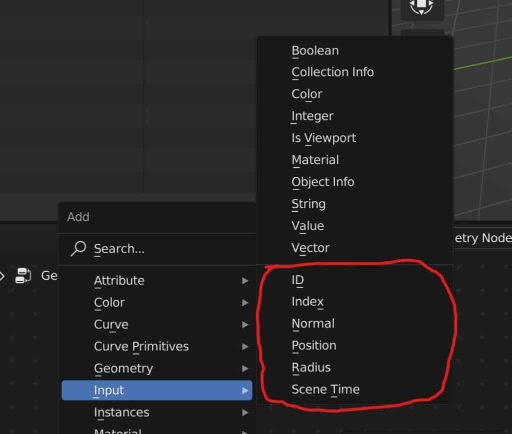
You will also notice that this is actually split into two categories that are not actually labelled, but they resemble two types of input nodes. The options that you see on the top half of this menu represents types of data that can be used to control our geometry node systems.
For example, we can use a vector node if we want to control another node using vector based data.
The options in the bottom half of the input menu represent attributes that actually stored data per elements.
Adding these attribute nodes and then connecting it to your setup will rarely change anything by themselves. However, what it is doing is calling your attribute to that node.
This means that you will be able to introduce more nodes that will use the data from that attribute to define the main set up and how it works.
If you want to learn more about Blender you can check out our course on Skillshare by clicking the link here and get 1 month free to the entire Skillshare library.
A List Of The Different Attributes Used In Geometry Nodes
There are many different attributes that we can use in Blender to control our geometry nodes systems. So below we have created a table that will that will demonstrate each of the attributes that exist within Blender, the domains in which they are stored in and the types of data that each attribute uses.
| Attribute | Domain | Geometry Type | Data Type | Description |
|---|---|---|---|---|
| Position | Vertex | Mesh | Vector | The location data of each vertex element on your model. |
| Normal | Face | Mesh | Vector | The direction that each face element is pointing. |
| Index | All | All | Integer | A unique value for each element within a domain. Starts from 0 and then increases |
| ID | All | All | Integer | A custom value generated by the user. Can be unique or shared. |
| Edge Crease | Edge | Mesh | Float | The amount of creasing applied to an edge to prevent it from being shaded smooth |
| UV Map | Face Corner | Mesh | Vector | Mapping vector that is used to help control texture application to faces created with geometry nodes. |
| Material Index | Face | Mesh | Integer | Value assigned to faces to match up that geometry with materials that have the same index value. |
| Shade Smooth | Face | Mesh | Boolean | A true or false attribute that determines if smooth shading is to be applied to a specific element. |
| Resolution | Spline | Curve | Integer | How many child points are generated between each control point to define the smoothness of the curve. |
| Is Cyclic | Spline | Curve | Boolean | Do the start and end points of the curve connect to form a closed loop. |
| Radius | Control Point | Curve | Float | Used to define the thickness of the geometry created around the curve. |
| Tilt | Control Point | Curve | Float | Used as a way of rotating points around the shape when adding thickness. |
| Vertex Groups | Vertex | Mesh | Boolean | A custom made attribute used to define a selection of vertices. Can have multiple vertex groups in a single nod set up. |
| Handle Left | Control Point | Curve | Vector | The location of the left handle of a control point. |
| Handle Right | Control Point | Curve | Vector | The location of the left handle of a control point. |
When sculpting or texture painting in Blender the best method is to always use a graphics tablet. But these come at many different price points and forms. If you want to get started with sculpting using a graphics tablet then we recommend this as your starting point. It served us well for over 4 years before we upgraded to a more expensive tablet ourselves.
How To Use Attribute Nodes To Control The Objects Shape
Now that we have a better understanding for what our attributes are and how this information is stored, let’s take a look at how we can use attribute nodes to control our shapes.
A simple example can be to use an attribute to define the positioning of a selection of vertices. The position attribute uses affected data to determine the location of each individual element within the vertex domain.
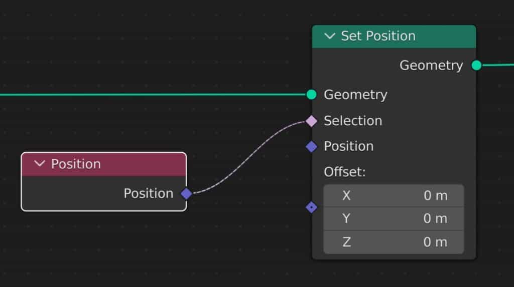
For our example, we are going to use the set position node to relocate the vertices of the top half of our cube.
Without any nodes to help define at the selection, the set position node can be used to manipulate the offset values to move the geometry as a whole on each of the free axes. By connecting nodes to the selection input, though we may be able to control which of our vertices are moved by this node.
We can add a position node and then connect it to these selection inputs. This will not do anything by itself, but simply having our position node allows the set position node to call the position data of each individual vertex.
We did need to introduce additional nodes that will allow us to define exactly how we want to use the position attributes for our selection.
In our example, the talk vertices of our cube are above the plane of the Z axis, which means they have a positive value. The bottom vertices, however, have a negative Z value as they are below Z plane.
We can start by adding a separate XYZ node and positioning it after the position node. Then we can connect the Z output to our offset.
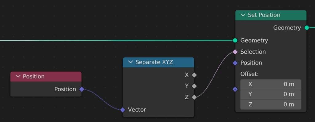
This now means that we are calling our position data and we are telling Blender to focus on the channel of our position factor while ignoring the data that comes from the X&Y channels.
Then we need to create an equation or formula that blender can use to define our selection based on the Z axis. For this, we’re going to use a math node and set it to greater than.
This means that any vertices greater than the threshold value will be affected by the set position node. We can set the threshold to a value of 0, which is the actual Z plane.
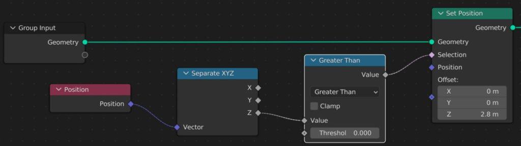
Now when we are able to manipulate the offset value of the set position node, only the top half of our cube is going to be affected by this nodes offset.
If we change the math operation to less than, we can invert this effect and only have the set position node affect our bottom vertices.
This is an example of where our attribute node, which in this case is position is used to call the position data of each individual element. We then use a separate XYZ node to dictate which of our three channels from that vector data we want to use. And then finally, we use a math node to create the formula required to determine our selection.
Thanks For Reading The Article
We appreciate you taking the time to read through the article and we hope that you have been able to locate the information that you were looking for. Below we have compiled a list of additional topics that are available for you to view and learn more about Blender.
-
Hair & Fur in Blender: Particle Systems
Creating realistic hair and fur with Blender’s particle systems.
-
Skin Texturing: Subsurface Scattering Techniques
Mastering skin texturing with Subsurface Scattering techniques in Blender.
-
Anatomy Modelling: Blender Muscle Guide
Sculpting anatomically accurate muscles with Blender’s powerful tools.