With geometry nodes, we not only can create single objects procedurally but also an entire scene using the geometry nodes workflow. A good exercise is to be able to create simple environmental systems like a hexagonal grid to position objects on.
To create a hexagonal grid, complete the following steps…
- Create a hexagon from a cylinder with the object origin at the base.
- With a new model, create a node system where we instance points to a mesh line node
- Use the object info node to instance the hexagon object across the mesh line
- Change the value of the Y offset in the mesh line to 0.866
- Use the set position node to control the position of your instances
- Add Index > Wrap > Greater Than > Vector Multiply to the set position offset
- Instance the entire setup to a second mesh line to create a grid on two axis
- Use combine XYZ to isolate the Z axis and a random value to randomize the scale
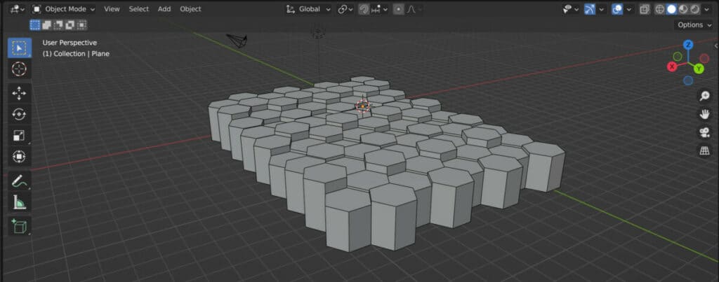
Once you complete the process, you should be able to create a hexagonal grid of any size and begin to randomize your grid using nodes like the random value node. From there, you can begin to create many interesting patterns and effects using your grid system.
Creating The Hexagon
Step one is to create the base shape of the entire grid, which is a hexagon. You can replace your cube with a cylinder and set it to have six sides.
If you want to go full procedural, you can add a geometry node system to that object and use a cylinder node instead of the group input. This will allow you to make changes to the base object more easily.
Either way, you should set the depth value, which is the size on the Z axis, to one so that it will be easy to work with later on.
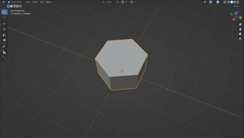
If you want the bottom of your grid to be level, move the object up on the Z axis in edit mode or by using a transform node in the node editor so that the object origin is located on the bottom face.
Apply your geometry nodes modifier if you used it to make it easier to apply modifiers later on.
Create A Node System For Your Array
The grid system is effectively an array of hexagons on two axis; usually the X and Y. Create a new model which will be replaced with the array.
Add a node tree to your second model and replace the group input node with the mesh line node. The mesh line will be used specifically for the X line of the grid.
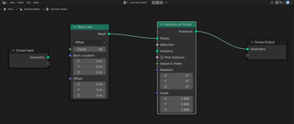
Next, add an instance on point node and connect it after the mesh line node. The object will disappear because no instances are currently being used.
Set your Z offset to 0 and increase your Y offset to 1 for the moment, but we will return to this value later.
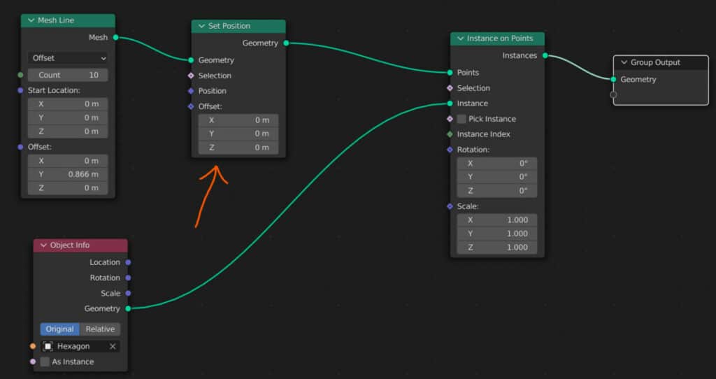
Use The Object Info Node For Your Instance
To use your object as the instance of your array, drag and drop from the outliner panel into the node editor to create the object info node for that model.
Connect the geometry output of the object info node to the instance input of the instance on point node.
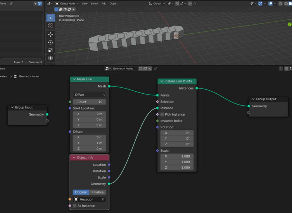
If you change the count value, you will see that the object is instanced at each point, so a count value of one generates a single hexagon.
The Correct Offset For The Shape
The hexagon will be positioned at the location of each point on the mesh line. However, you will notice the shape overlapping.
The solution here is not to increase the offset value in the Y axis, which initially does appear to create the gap.
But to create a locked grid, each array needs to have two lines of hexagons that alternate their position. And these lines need to lock in together.
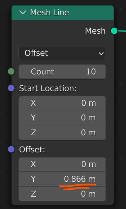
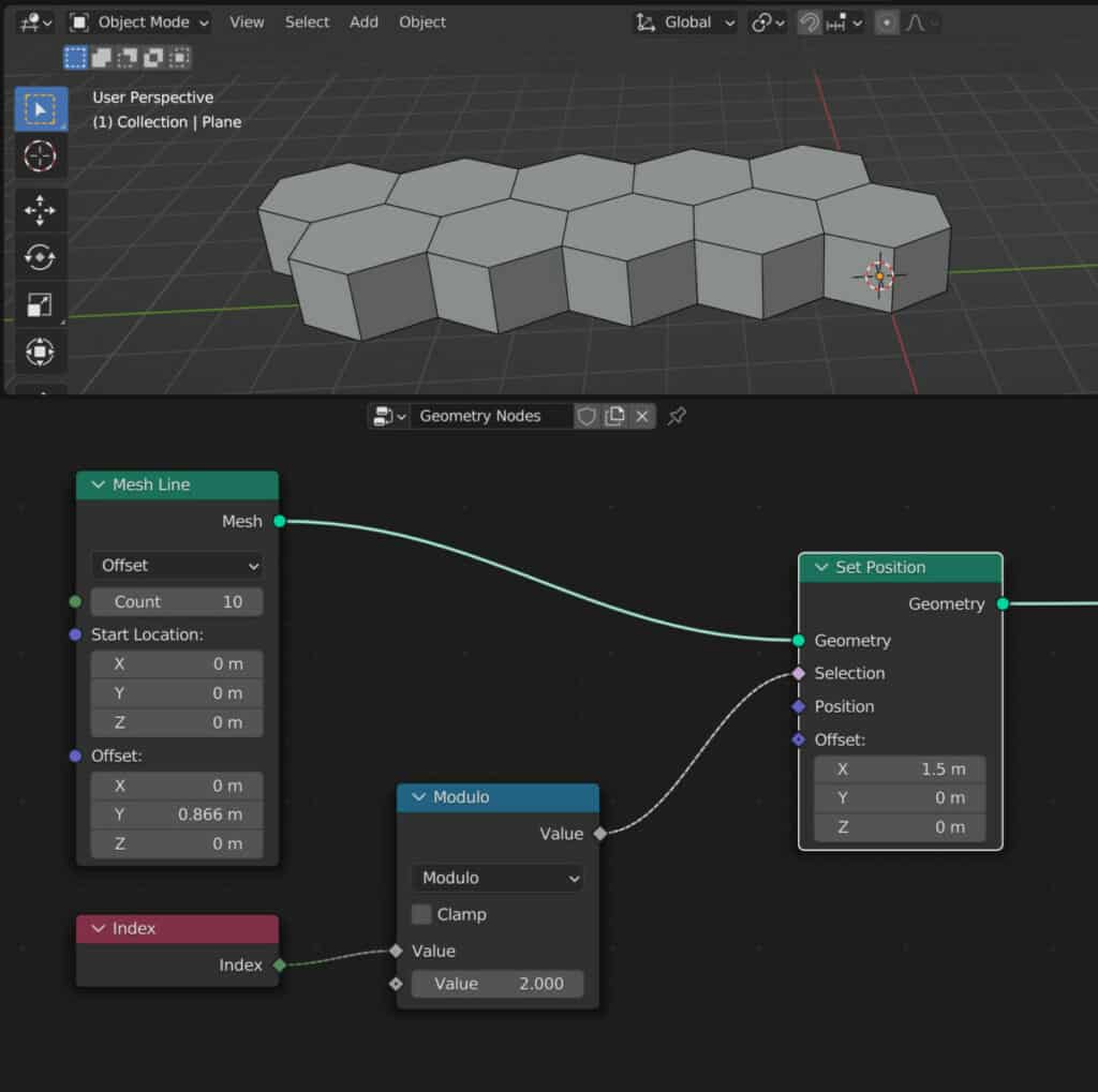
The value we will use for this is 0.866 on the Y offset, which brings the instances closer. But you will see why we do this when we create the second line.
Adding The Set Position Node
We want to move half of the instanced hexagons up on the X axis, so that we create two alternate rows of hexagons.
To do this, we need to add a set position node in between the mesh line node and the instance to point node.
By default, this will allow us to move the mesh line using the offset vector. We now want this only to affect half of our points.
Setting The Position Offset And Isolating Instances
The offset allows us to move our points so that we will look to change have the offset works by adding an index node.
Each instance will have its index value when generated, which will act as its unique identifier starting from 0 and increasing with each point added along the mesh line.
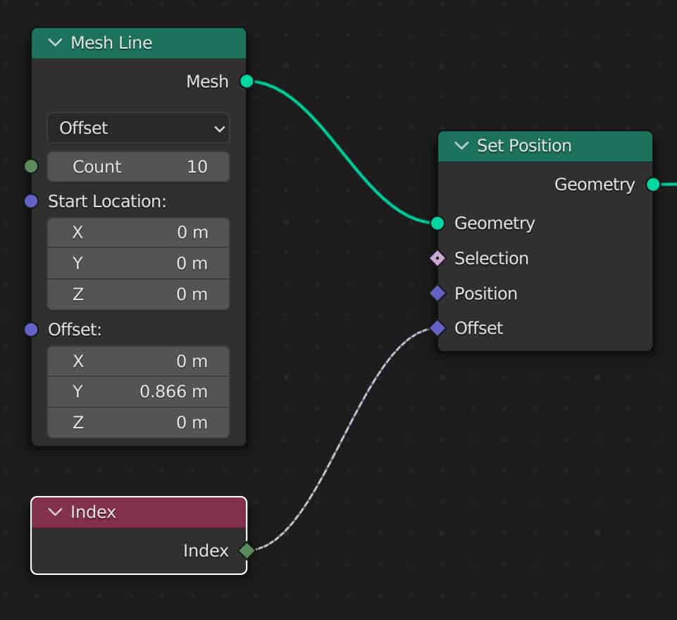
When connected to the offset directly, the position of each point will be the same as its index value with each axis. This is why you may notice the array move across three axis instead of one.
To alternate the selection, we will add a math node and set this to the modulo operation, which will use a 0 to 1 range for defining the index values when we set the value to 2.
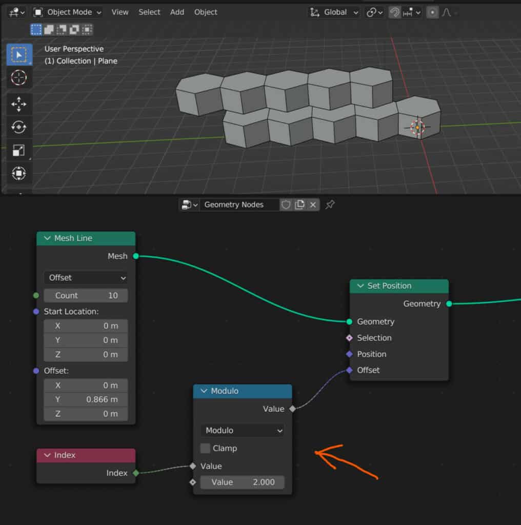
This means that each instance will have a value of either 0 or 1. Any instance with an index of 0 will remain where it is, while any instance with a value of 1 can be moved.
To move out instances on the X axis, introduce a vector math node and set it to multiply. For the X value, set this to 1.5.
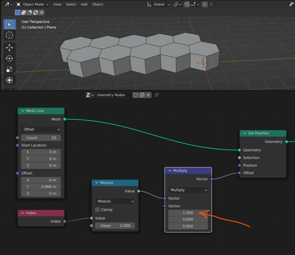
The hexagons will now be diagonally spaced on two axis.
You can further reduce the number of nodes used here by removing the vector math node and plugging the modulo into the selection instead. Change the X offset to 1.5 to achieve the same result.
Create An Instance Of Your Setup To Use On A Second Axis
By this point, you can generate an array of hexagons on a single axis. The quickest way to replicate this on a second axis is to instance the entire setup.
Add a second instance on point node and position it directly after the first. Detach the connection from the point input and plug it into the instance input, as the entire setup so far will be used for the following array.
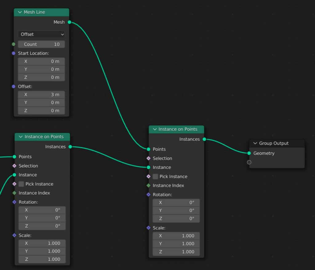
Add in a second mesh line node and connect it to the points input. Then set the Z value to 0 for the offset and the X value to 3.
The reason it needs to be set to 3 is that the length of any one hexagon on the X axis is 1.5, and because we have two rows of hexagons, we need to double this value to get the array to fit correctly.
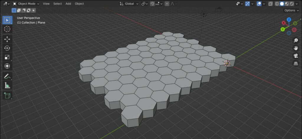
If we change the values of each mesh line node, we should have complete control of the size of the hexagonal grid, with all instances fitting together nicely.
Randomizing The Scale Of Your Instances
Now that we have our grid, we can do much with it. One example is to randomize the scale of our instanced geometry.
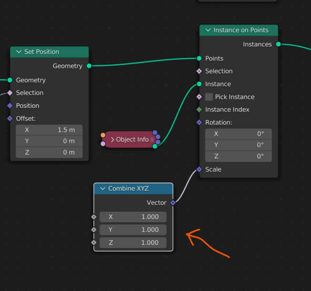
To randomize the scale on the Z axis only, add a combine XYZ node and attach it to the scale of the instance on point node.
Set all values to 1 to start with, then introduce a random value node. Connect the random value node to the Z input.
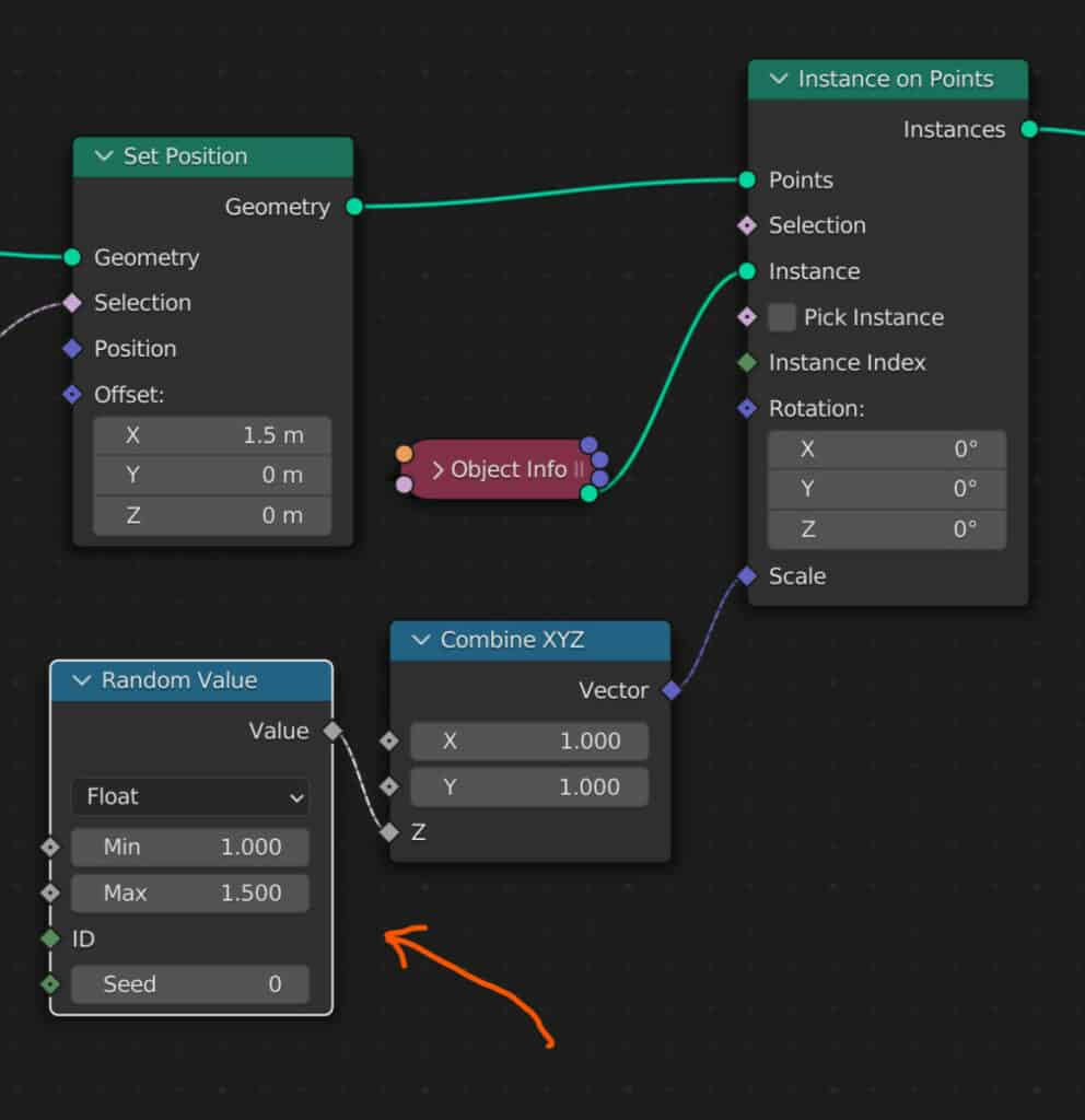
Choose the values that you want for the min and max values. For our example, we use a min value of 1 and a max value of 1.5.
You will notice that this is not completely random, as it replicates on the second array. Connect the same combine XYZ node to the second instance on point node to improve the randomization.
Thanks For Reading
We appreciate you taking the time to read through the article, and we hope you found the information you were looking for. If you are interested in learning more about geometry nodes, look at some of the related articles we have listed below.