When working in geometry nodes, some of these nodes are going to be used a lot more than others, and one of the most frequently used nodes is the math node which can be used in combination with almost any other type of node in Blender.
To add a math node into your geometry nodes system, open up the add menu with Shift + A. And then go to the utility’s sub-menu. Select math from this list and that will add the math node to your node tree. To change the math nodes effect, go to its Operation menu and change the current operation.
A single math node has the potential to change the entire way that you’re node tree affects your model. It is also one of the most common nodes for exposing parameters to your geometry nodes modifier and can even be used to better control other values such as an object transforms.
How To Create Shapes Using Math Nodes
A great exercise for learning how to make the most of math nodes is to view how they change your models visually. We can do this by using a special mesh primitive as our base object. This primitive is known as the mesh line and can be accessed from the add menu under mesh primitives.
If we want to be able to create shapes using our math nodes then we will need to set up our node tree a certain way, starting with the mesh line node.
Understanding The Use Of The Mesh Line Node
The mesh line node is the perfect starting point if you want to have complete control of your 3D model’s shape, because it is not three dimensional. It starts out as a simple line formed of multiple vertices and edges that all follow a single direction to make it look like a single edge.
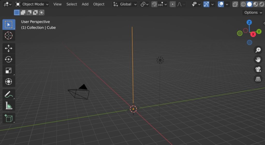
Because the mesh line node is a mesh primitive, it is often used to replace the group inputs geometry. This means that unless you begin to expose parameters, the group input will not be connected to the node system.
Of course, this is exactly what is required. In order for us to create any shape that we want, we can’t be starting off with an existing shape that potentially limits our flexibility.
Using the mesh line node by itself, we can determine both the length and the direction of the line as well as the number of points used to construct it.
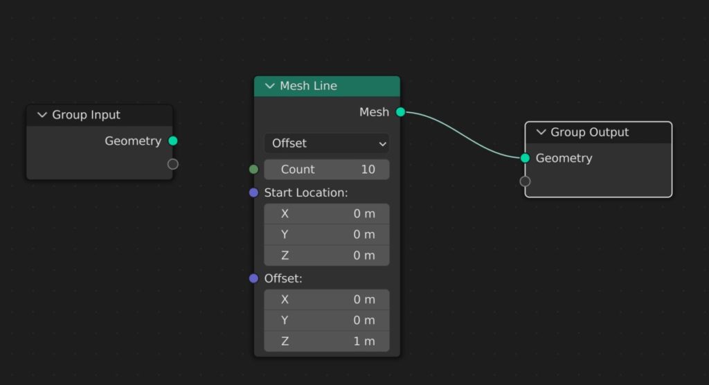
There are two modes that we can work with for this calculation. We can either use the endpoints mode or the offset mode.
For the offset mode, we start by defining the factor location of the first vertex in our mesh line, which by default will be at 000.
We then determine how much space will be between each of our points. In other words, the offset. This would allow us to not only control the space between our points, but also the direction that the line will go in.
By default, this is set to 001, which means our line will be traveling along the axis. Manipulating these values will change the direction of the mesh line.
We then determine the total length of our mesh line by manipulating the count value. The higher the count, the more points are created, but the distance between each point will always be the same based on our offset vector.
By contrast, we can also use the endpoints mode to determine our length and direction. Within the endpoints mode, the offset is replaced by the end points vector. This now means to whatever the second vector is in this node will be the location of the final points of your mesh line.
The Count integer will still increase the number of points along the line, however, it will no longer increase the length of the line as this has now been predetermined by the start and end points.
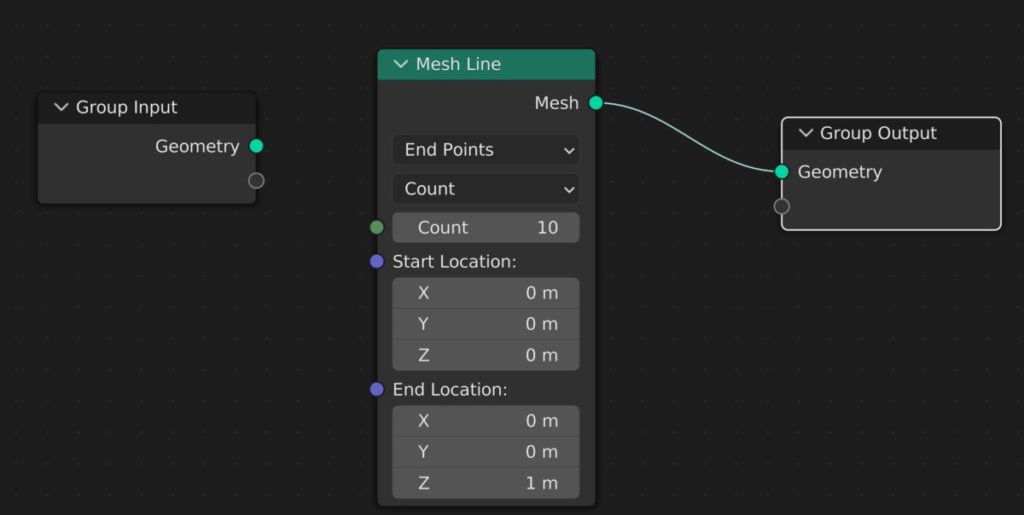
In this mode, you also have the opportunity to change between count and resolution. If you choose the resolution value, then in order to increase the number of points on your mesh line, you will need to decrease the resolution value.
For example, if your line was one meter in length and you wanted to create approximately 10 points, then you would want to use a resolution value of 0.1. This means that a point would be added every 0.1 meters along the mesh line.
However, the resolution value adds points to the starting points, which means that if you were to set the value to 0.1, you would add 10 points to the original, which means you would have 11 in total.
While this does not allow us to change the actual shape of our mesh line, it’s important that we understand exactly how the mesh line node works so that we can then combine it with other nodes to begin manipulating the shape.
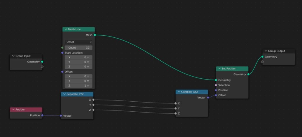
Setting Up Your Node System To Begin Creating Shapes
For us to begin creating our own shapes using the mesh line node, we node to gain control of the positioning of each point on the mesh line, and have further control of the three vectors of each point, which are on the X, Y, and Z axis.
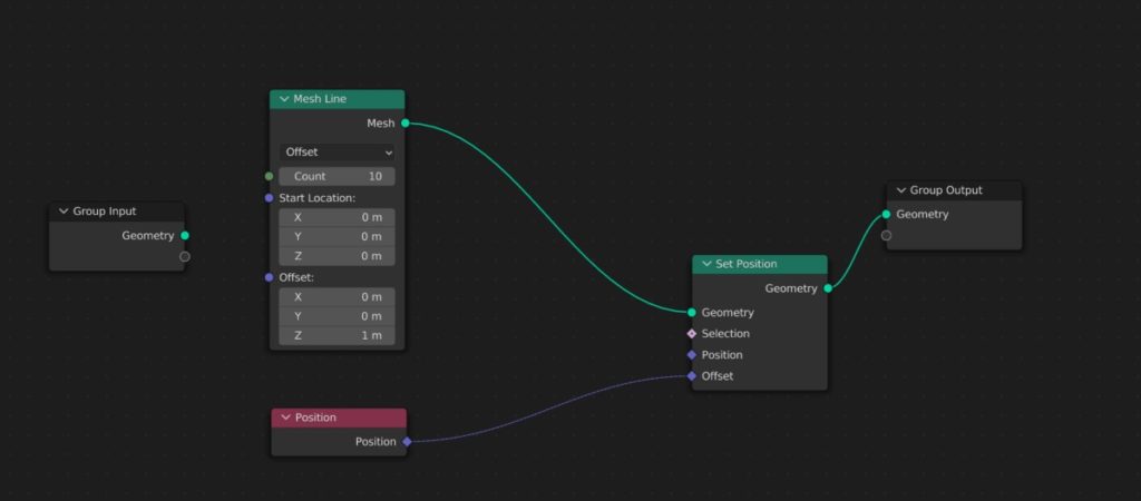
To change the positioning of our elements we need to use the set position node and place it directly after the mesh line node. Then we need to control the position of each point using the offset vector.
Adjusting these values as they are will only move the line as a whole and will not reshape it in any way. The next step therefor is to isolate the vector channels so that we can control them independently.
These channels are stored within the position attribute of each element, and so we will need to call this attribute first by adding a position node and attaching it to the offset input.
Of course, merely calling the position attribute is not enough, and we now need to create a set up that allows us to a) separate the position vector into three channels, b) allow us to edit each channel, and c) combine those channels before reaching the offset input.
For step a, introduce a separate XYZ node after the position node. Then go straight to step c and include a combine XYZ node that will go right before the set position node.
Now you should be able to connect each of the outputs from the separate XYZ node into their corresponding inputs on the combine XYZ node.
Creating A Basic Circle Using Math Nodes
Once you have the correct setup you will be able to begin creating your own shapes by manipulating the points of the mesh line node using math nodes.
To add a math node, press Shift + A on your keyboard to open the add menu, then go to the utilities sub menu and select math, and position between the separate and combine XYZ nodes.
All shapes are created using algebraic formulas, where X = Y in an infinite number of variations. Or perhaps X = Z, as we have three values to work with.
For example, if we reconnect X with Y, then Y will receive the initial values of X from the mesh line node.
Every shape imaginable can be generated using a specific formula, and these formula can be created using our node set up which isolates the vector channels.
By connecting the X output to the Y input we are creating the formula Y = X. We can increase the complexity of the formula by introducing math nodes to the connecting noodle.
If we introduce a math node and set it to the add operation, and refer to the node itself as C, then we create the formula Y = X + C.
The creation of actual shapes requires us to be a little bit more creative, so let’s skip ahead to the formula that we use to create a circle which you can see below.
The Best Place To Learn Geometry Nodes?
Geometry nodes differ from the traditional form of modeling as it acts as a system that the artist can control to both create and change the models in their scenes. The best way to learn this system is by using our own.
The Blender boot camp is an educational resource dedicated to teaching Blender and Blender alone. The geometry nodes boot camp is our tailor made course to learning the node system from the ground up.
If you are looking for the best resources to get you started though, we are offering our free geometry nodes starter kit, which contains our beginners guide to geometry nodes along with our procedural building asset pack and geometry nodes terminology cheat sheet.
Click on this link to access these resources for free
Learn More About Geometry Nodes From These Articles
We hope that you find this article useful for accessing the geometry nodes system. If you want to learn more about how you can use geometry nodes, then check out these articles listed below.