Most of the time, when using Blender, we typically use the axes of the 3D World. However, we can use other axis known as transform orientations to change how tools are affected by our transform orientation.
Bellow is a list of the different transform orientations we can use in Blender…
- Global
- Local
- Normal
- Gimbal
- View
- Cursor
- Custom
Most of the time, you are likely only to require the use of the global orientation axis, and sometimes the local, while working with objects in edit mode. However, there are use cases where any of these transform orientations can be valuable.
Using Global Orientation As The Standard Axis
The default orientation for Blender users is the global orientation. This relates to the X, Y, and Z directions of the 3D World itself.
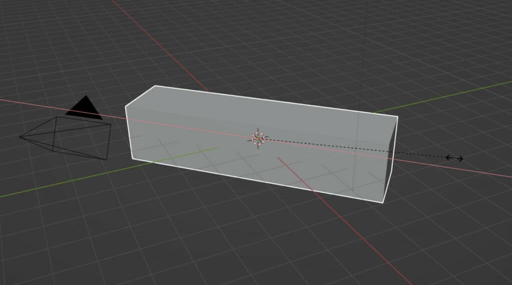
For example, when we grab an object in the 3D viewport and then look the location tool to the X axis, we can move our object along the X axis of the 3D World.
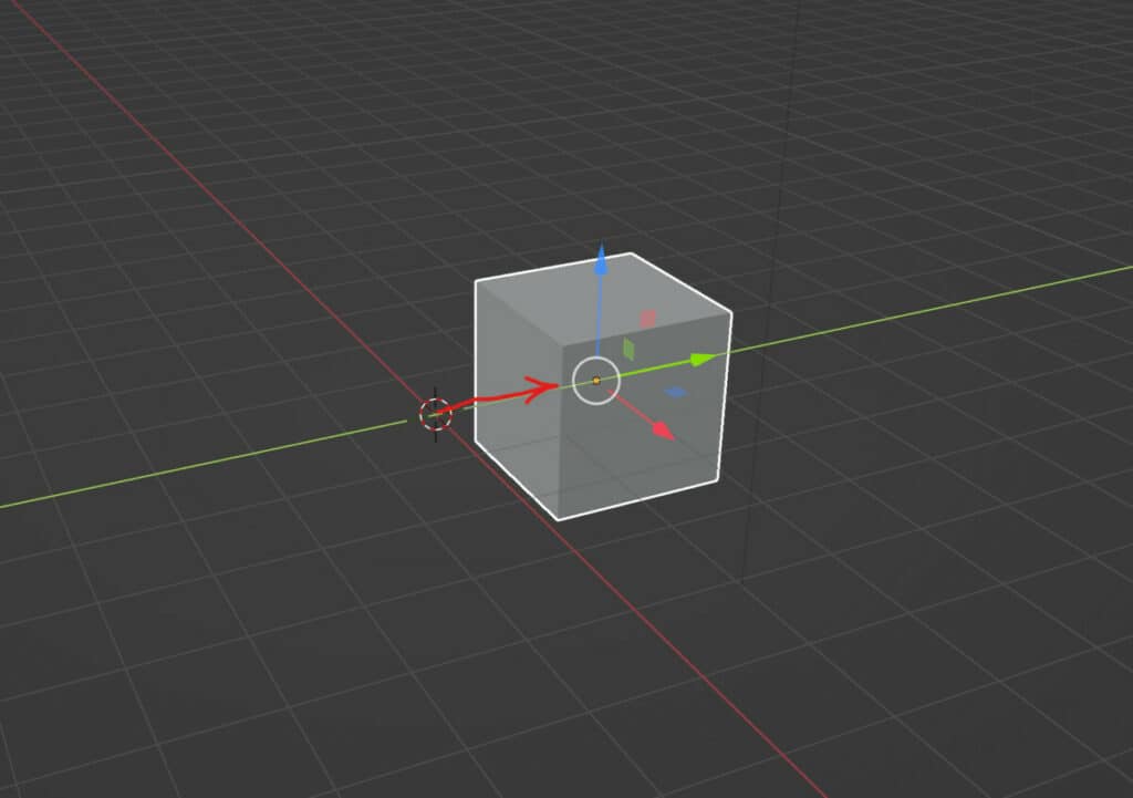
If we were to rotate our model and then perform the same function of grabbing and moving our object along the X axis, it would still follow the same direction because it is using the 3D viewports X axis and not that of our object even though it has been rotated.
Global orientation is therefore used in most situations where we are positioning our objects within our scene.
Accessing The Other Orientation Methods
If we want to select a different orientation to use, we need to locate the orientation tool which is in the center of the 3D viewports header bar.
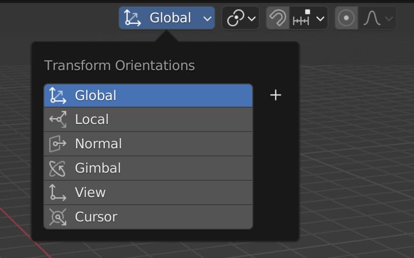
You should see a button with an axis icon and the global label, allowing you to open up a menu when you press the left mouse button.
From here, choose any of the orientation methods you plan to use.
Using The Objects Local Orientation
Aside from the global orientation, which you will use most of the time, the second option is the local orientation. The critical difference between this type and the global type is that it uses the axis of the object itself rather than the 3D world.
This means that transforms such as the rotation will change how other tools are affected.
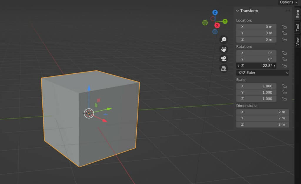
For example, let’s rotate a cube object 45 degrees on the Z axis. In our global orientation, this would not affect the ability to change the location or scale of our model. If we hit the G key while in global orientation and lock it to the X axis, it will still move along the red X line.
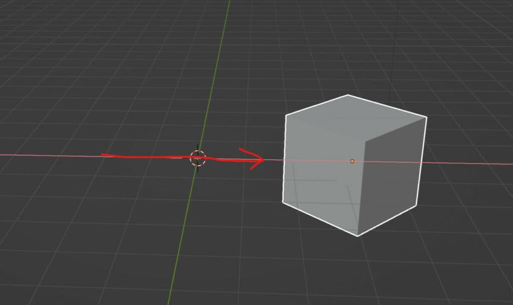
If we were to scale on the X axis using global orientation, we would see that it does scale on the X axis, but the scaling operates differently because of the rotation.
The effect of both transforms to change is if we were to transition from global orientation to local orientation from our menu.
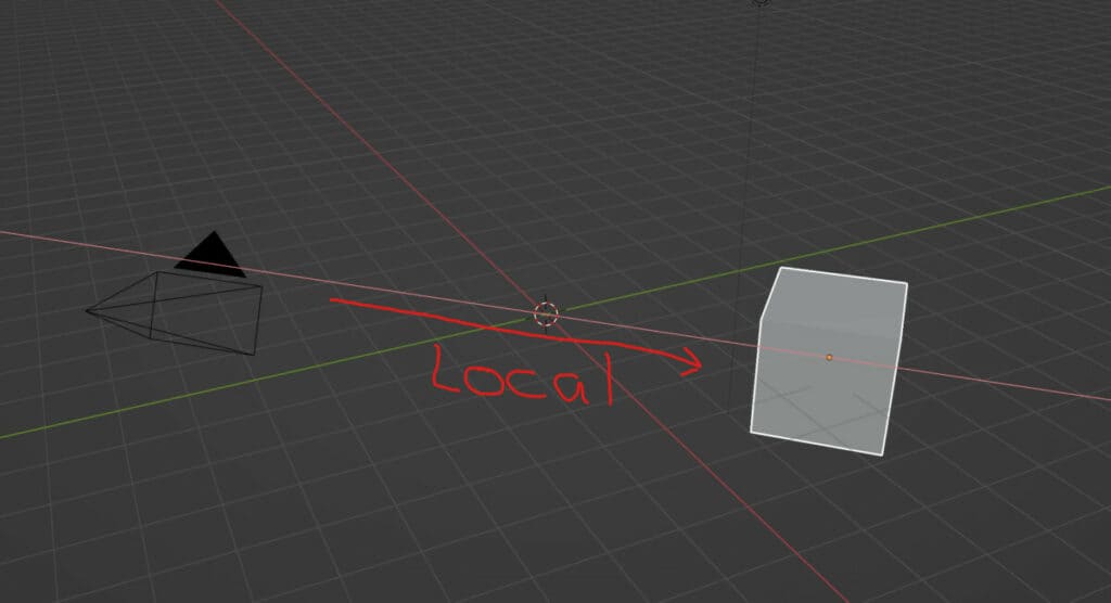
If you change the local orientation and press G, then X to lock the location on the X axis, you will see that the red line now appears diagonal.
We are then able to move our object along its own X-axis. So after rotating the object on the Z axis, we effectively change where the local axes are pointing.
This also affects the scale transformation. If we were to use the S key to enable scaling and then use the X key, we would see that the scale works as it would have done at the start of our example before we rotated, except the scaling is being done diagonally instead of straight along the global X axis.
Normal Orientation Versus Local Orientation
The next orientation method on the list is the normal orientation, which initially will appear to be the same as local orientation when used in object mode.
If we go back to our rotated cube example, normal orientation will allow us to move our object and scale it in the same way that the local orientation would.
This is because the normal orientation is not used with every object type and is primarily used with objects that have geometry, such as mesh models.
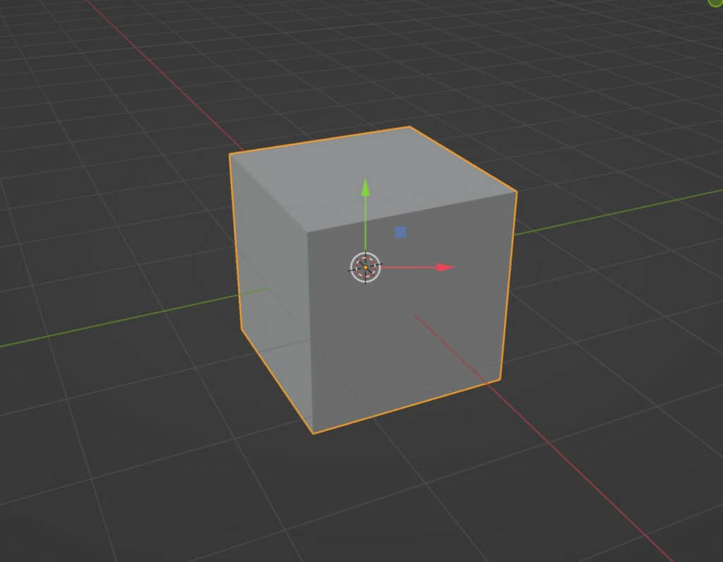
Before transitioning into edit mode, I will reset the cube to its original rotation. This will make it easier to see the difference between normal and local orientation.
Then use the TAB key to transition into edit mode. If we were to switch between global, local, and normal orientations, at this point, we would not see any change in our ability to grab, rotate and scale.
To display the difference between the orientation types, activate the grab tool to display the 3D gizmo. For all orientations, the gizmo will initially point in the same direction.
This will change if you select a specific piece of geometry, like a face. Select one of the side faces of the cube and then switch between local and normal orientations.
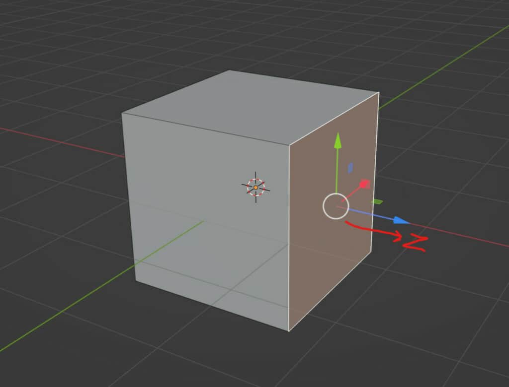
You will notice that the orientation of the gizmo changes so that the Z axis is always pointing our from whichever face you choose to select.
The reason why is the normal orientation will always use the Z normal of the selected geometry, which is why it only works in edit mode where the geometry can be selected.
This makes normal orientation useful when editing the models themselves.
Not only does normal orientation apply to faces, but it can also be used to control edges and vertices. Selecting an edge on your cube will view the Z normal pointing out diagonally, based on the edge angle.
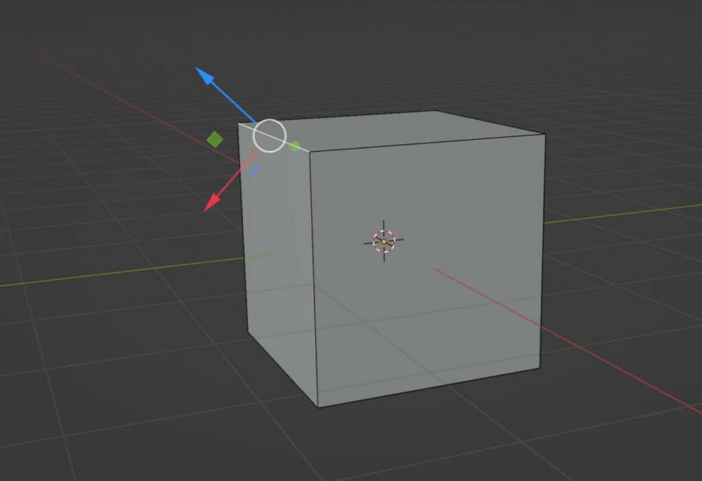
Changing the cube’s shape to reduce the edge’s angle changes the Z normal of that edge. A similar concept is applied to vertices as well.
Using The Gimbal Orientation Axis
In practice the gimbal orientation method is a more advanced version of Local orientation with more control. It implies using a euler calculation to define the direction of each axis.
Rotate the cube by 45 degrees on the X axis and test the Global, Local and Gimbal options. Of the three the Local and Gimbal axis appear the same, but with gimbal we can change the Euler mode.
Press N to open up the side panel, and under rotation for our object you will see a menu button labeled as XYZ Euler.
Select the option to bring up the menu. The difference between the options here is the order in which the gimbal processes the axis. Using the default XYZ method, rotating on the X axis does not change the gizmo at all.
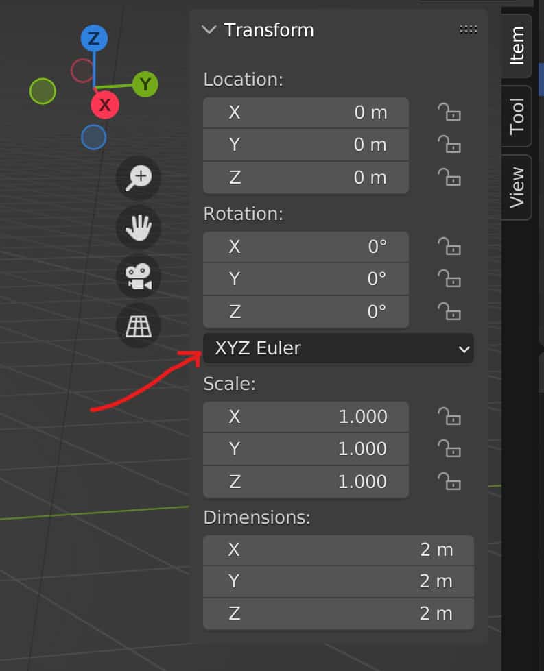
However, if we rotate the object on the Y axis, then the X arrow begins to rotate with the object, and if we rotate the Z value both the X and Y arrows of the Gizmo are rotated.
The Z axis is the control for this euler method, and we can change the order of control by changing this euler method.
Setting the method to ZXY for example, will use the Y axis as the control, so the green arrow never moves when the object is rotated.
The final option here is for the axis angle, which allows you to set a value in radians on each axis to define the influence of that axis.
For example, setting the Z axis to 1.00 and then rotating the W value by 45 will rotate the model by 45 degrees on the Z axis.
Manipulating Your Transforms Based On The View
Of all the transform orientations this is the easiest to understand. It is the only orientation that uses two axis instead of three, as the axis is based on the view within your 3D viewport.
Only the X (Horizontal axis) and Y (Vertical axis) are used with this transform orientation. The appearance of the gizmo in the viewport is constantly the same as it matches your view angle.
While easy to understand how it works, the view orientation can be tricky to use, as it requires you to line up your view so that you can grab, rotate and scale your model along the desired direction.
Use Your 3D Cursor As Your Orientation
The next option that we have for transform orientations is to use the 3D cursor. Like the view option, this involves not using our objects at all to define our orientation.
Like all of the various object types within the 3D viewport, your 3D cursor has a location value and a rotation value.
To access these values, press N to open up the side panel if you have not already done so, and then go to the view tab in the side panel.
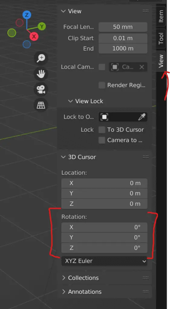
Towards the bottom of the view tab, we will have access to the location and rotation values of our 3D cursor.
If we manipulate the X, Y, and Z values of the 3D cursor, we will see the changes mirrored with our gizmo.
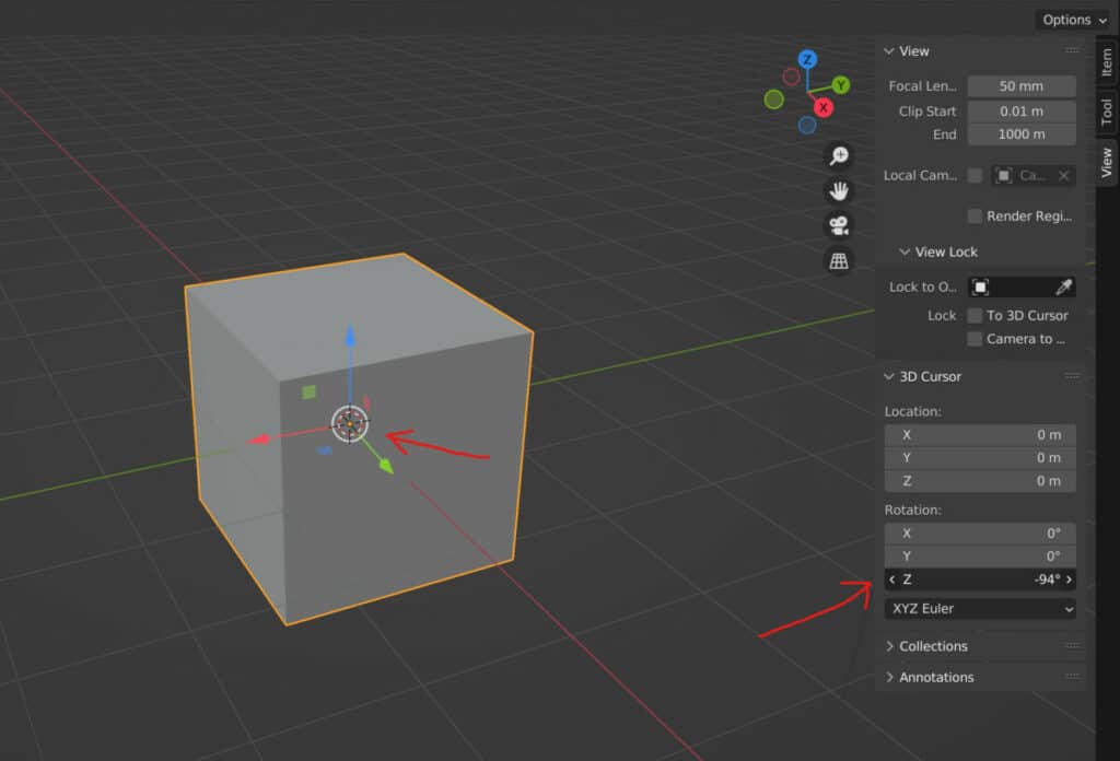
For example, changing the Z value will begin to move the X&Y arrows on our gizmo. This way, we are able to use the rotation values of our 3D cursor to define the orientation of our transforms.
Creating Your Own Orientation
The final option is to create your own orientation. If you take a look at the orientation menu, you will see that there is a plus button on the side.
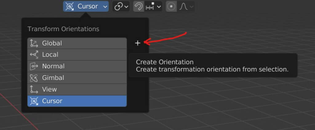
Before clicking on that plus button, use one of the other orientation methods to redefine your axes directions. For example, we can click on the cursor option and rotate the cursor 45 degrees on the Z axis.
Then we can go back to our orientation menu and click on that plus button. This will create a new orientation which we can rename. For our example, we will rename it 45Z.
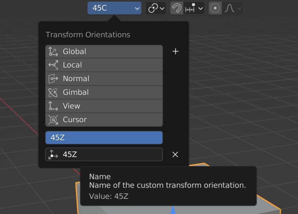
Now we can access our custom orientation whenever we want, and we can even go back to the cursor orientation method and begin to manipulate that without changing our 45Z orientation.
This can be useful if you are arranging a scene from a specific perspective and you want to be able to move your objects along that perspective.
Thanks For Reading
We appreciate you taking the time to read through the article. We hope you found the information you were looking for. If you are interested in learning more about the Blender software, you can check out a few of the articles we have listed below.
- The Different Ways That We Can Use Our 3D Cursor
- What Is The Object Origin And The Various Ways That It Influences Our Objects
- The Different Ways That We Can Use The Pivot Point System
- The Various Methods Of Selection In Blender
- What Is An Empty Object And How Can We Use It