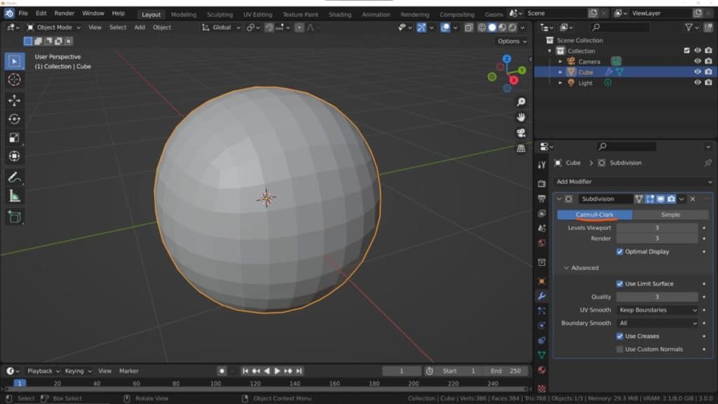
When using the normal subdivide tool we are able to add geometry across our model in a uniform manner without changing the shape of the model at all. However, when the subdivision surface modifier is in use our model deforms into a more spherical, curved shape, even in areas where the model needs to remain sharp.
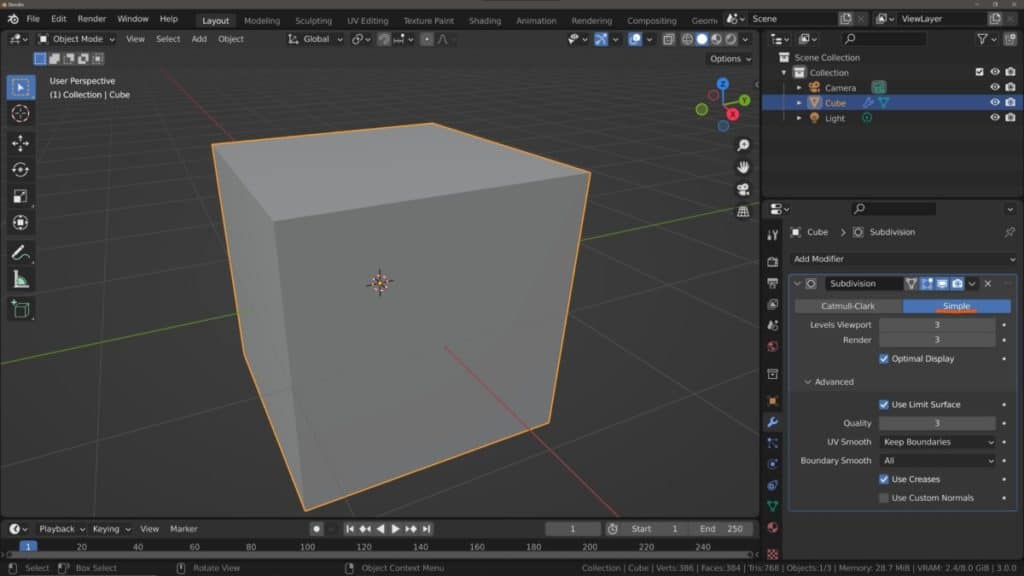
To keep edges sharp when using the Subdivision Surface Modifier, go to the modifiers tab and change the method to Simple to prevent deformation of the base shape. You can also control individual edges by adding a crease value to the edges that you want to keep sharp, limiting the effect the modifier has on the shape.
The option that you choose will be dependant on just how much you want the subdivision surface modifier to affect the shape of your object, if not at all, change the modifier to simple. And if you want to use the modifier to shape your model, then assign creases to your edges.
The ‘Simple’ Method Of Keeping Your Objects Shape With Subdivisions
When using the subdivision surface modifier as a beginner you may find its functionality to be both a blessing and a curse. It is a fantastic way of adding geometry quickly to your entire model and helps to add curvature across the edges of your object to create a more natural look.
On the other hand, you may only want to use the modifier to add more geometry and not change the shape at all, which can leave you a bit frustrated when you compare it to the subdivide tool, which by default only adds the geometry.
The problem with the subdivide tool is that it is destructive. The change that we make with the tool is permanent on the model, so we can’t make changes to the tool later on.
With the modifier though the fix is simple. Subdivision surface can apply one of two methods to your model. The default method is the Catnell-Clark method and is used to not only add the geometry but also reform the mesh to improve curvature, creating a more organic appearance.
The second option is the simple option that only increases the geometry with the modifier, and does not change the shape of the model.
What If You Want To Only Keep Certain Edges Sharp?
Depending on your modeling workflow, you may use the subdivision surface modifier as a tool that helps shape your models during the modeling process, rather than as a preview to see the model with extra geometry.
As such you can use certain modeling techniques in combination with the modifier as part of a beginner-friendly workflow that grants you the power to create highly detailed objects quickly while in practice working with a lower level of geometry.
One tool that you can use is the crease tool, which sharpens the edge and tightens up the geometry depending on the values used.
For example, in the image below we are in edit mode for a subdivided cube using the modifier. A total of three subdivisions have been added to the model but with the current settings, we are still able to see the base shape.
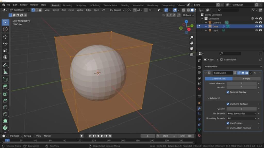
You can see that the shape becomes more and more spherical as we increase the number of subdivisions. For the next step, we use the face select mode and select the top face. You can also select the individual edges using the edge select mode.
Open up the side panel in the 3D viewport by pressing the N key. The first tab in the side panel will be the item tab where you can control the transform properties of your selected geometry.
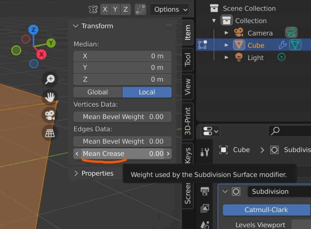
One of the options here is the Mean Crease value, set to 0 by default. If you only select a single edge then this will instead read as Crease.
In the next image, we increase the mean crease value to 1, and doing so tightens the geometry closer to its original form. It does not look like a cube, but nor does it look like a sphere.
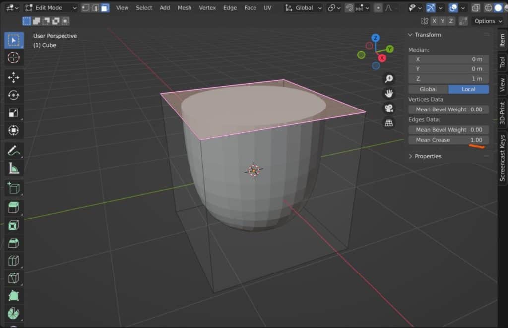
Again the higher the crease value the more the geometry will try to resist the modifiers’ effect on its shape. Note that the mean crease value does not in any way affect the amount of geometry that is added by the modifier, only its shape.
In the fourth image, we repeat the process with the bottom face of the cube. Selecting the bottom face and then increasing the mean crease value to 1.
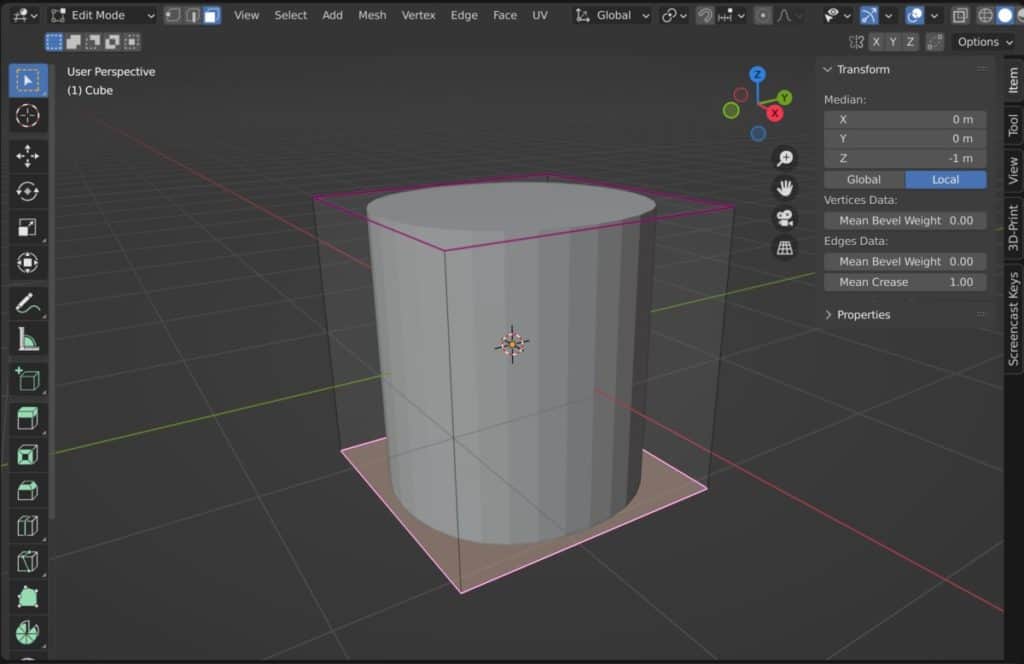
The result here is something that actually looks like a cylinder, rather than a cube or a sphere. But what’s interesting about this cylinder is that if you apply the modifier and go back into edit mode, you will see that the topology is different from the standard cylinders made in Blender.
Changing The Mesh With Other Tools?
While we prefer to use the crease tool ourselves as the primary means of control for the subdivision surface modifier, you can create a similar effect by adding geometry close to the existing edges using other tools.
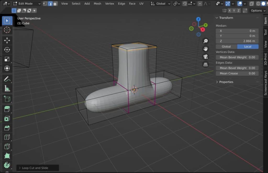
A common method over the years has been to add loop cuts to the model and push them close to the edges. The image below is an example of a loop cut being created and positioned to reshape the mesh without the need of the crease tool.
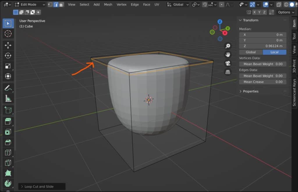
While this does work, it has one disadvantage compared to the crease method. With the crease method, you control the influence that the modifier has over the geometry, but with the lop cut method, you add geometry to those areas of the model.
This means that areas around the outline of your object will have denser geometry than other parts of the model, which can make modeling more challenging the more geometry you need to work with.
It also does not create a hard edge, even when the loop cut is pushed right up against the existing edge (Which you should avoid doing by the way).
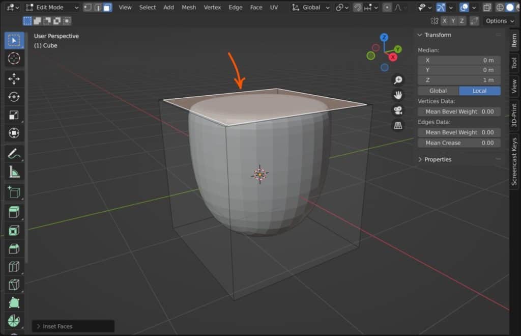
Another tool that impacts the shape in a similar way is the inset tool, which starts at the point of the existing geometry and is great for creating flat surfaces with the subsurf modifier.
Deleting The Face
The subdivision surface modifier requires the use of the objects face data to divide up the existing and faces and then reshape the model using the new faces. But what if there is no face to subdivide?
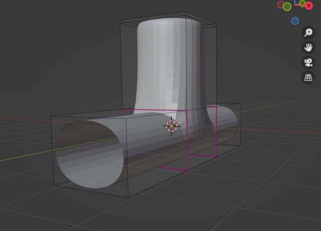
Below is an example of a curved pipe object, where we have used the techniques mentioned above to create an object in the form of a pipe.
This is an example of an object where it may be beneficial to have a hole in the model, but the ends are filled night now and the modifier has created that spherical appearance.
Select the face at the end of the pipe object, press the X button to open the delete menu, and then choose the delete face option. You are then left with the shape scene in the next image.
Because there is no longer a face at the end, there is no geometry at the end. Therefore the model creates a hard edge for the hole, which is perfect for a pipe.
Thanks For Reading The Article
We appreciate you taking the time to read through our article and we hope that it provided you with the information that you were looking for. Take a look at some of the other articles that we have here at blender base camp.
- Why Does Blender Crash While Modeling?
- How To Retopoligize Your Model The Fast Way?
- Troubleshooting Problems With The Subdivision Surface Modifier
- How To Unsubdivide A Model In Blender?
- The Main Purpose Of The Mark Sharp Tool?
-
Animation-Ready Hard Surfaces in Blender
Preparing hard surfaces for animation with optimized topology in Blender.
-
Symmetry for Hard Surfaces in Blender
Ensuring symmetrical perfection in hard surface models with Blender.
-
Detail with Shrinkwrap: Blender Modelling
Achieving intricate detailing with Blender’s Shrinkwrap modifier.